00195193-02 SG D4 FSE en (1).pdf - 第284页
Modular conveyor Conveyor Settings Setting and checking the la ser light barrier for the stopper position S tudent Guide SIPLACE D4 (FSE) Modular conveyor EN 09/2006 268 1 1.3.6 Setting and checking the laser light barri…
Modular conveyor
Width adjustment unit (Driver) Conveyor Settings
Student Guide SIPLACE D4 (FSE)
EN 09/2006 Modular conveyor
267
X Place the driver at the final dimension of 2/10 mm, press the actuator onto the final dimension and
fix with the screw.
X Actuators on all conveyor sides have to be checked and maybe adjusted.
X
Calibrate the conveyor
with SITEST.
11.3.5.2 Setting the ’pneumatic cylinder BERO’ on the driver
X Start SITEST
X Set any conveyor width. The adjustment units are positioned directly under the conveyor side.
X Start the I/O menu.
X Activate the pneumatic cylinder.
X Set the proximity switch on the pneumatic cylinder so that the LED (H36/H37 TSP 301) (H64/65
TSP 201) shines when connected.
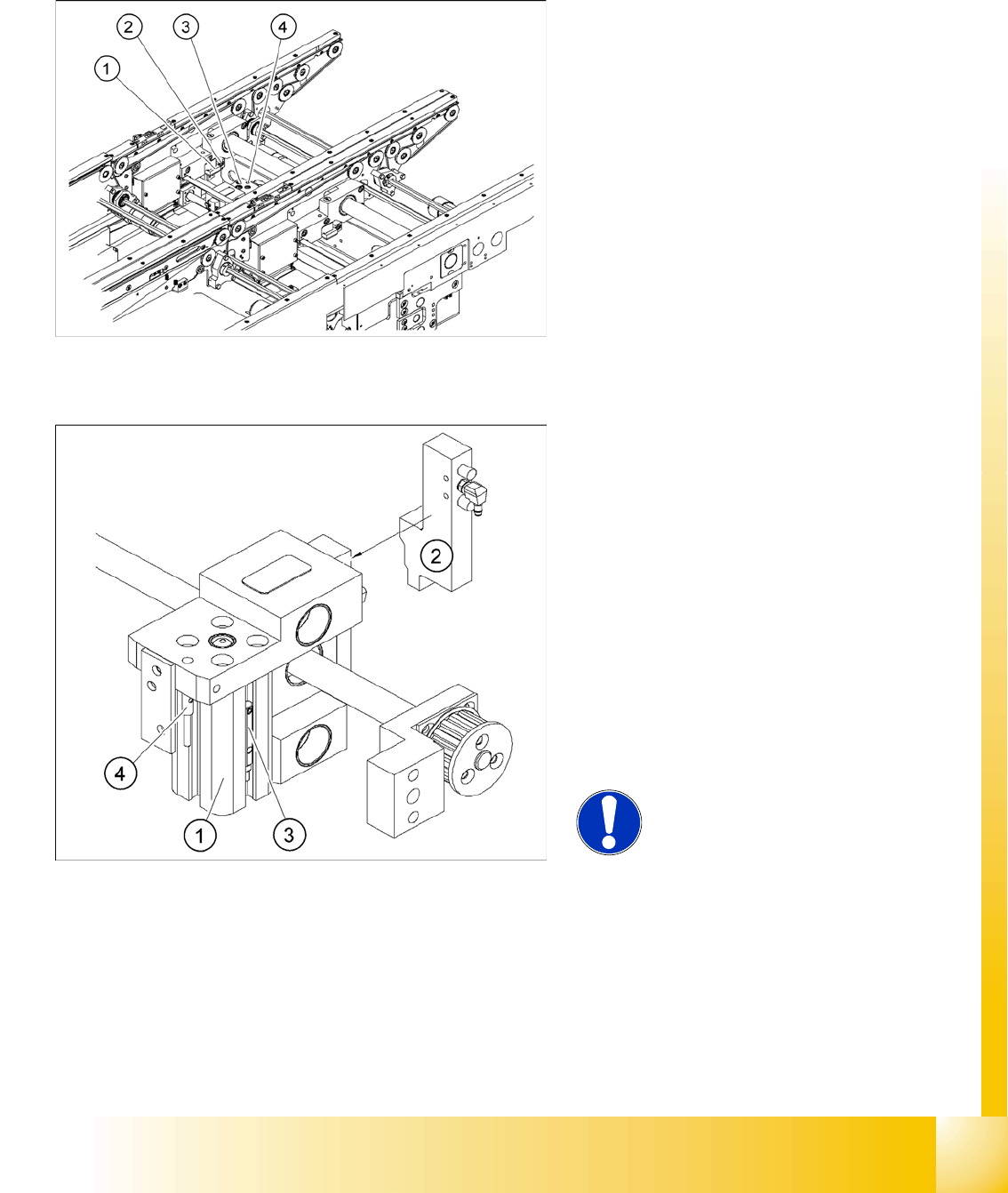
Legend:
1. Actuator
2. Actuator fixing screw
3. Driver
4. Proximity switch, adjustment unit
Legend:
1. Pneumatic cylinder
2. Solenoid valve
3. Proximity switch for pneumatic cylinder (for
"locking pin up" recognition)
4. Proximity switch for adjustment unit(for
conveyor side recognition)
The proximity switch (3) on the adjustment unit
cylinder should operate when the adjustment
unit pin is pushed out by the pneumatic
cylinder and therefore connected to the
conveyor side. This signal enables the width
adjustment motor.
NOTE:
The BERO on the pneumatic cylinder
is set.
The proximity switch is off when the
cylinder extended into free space.
Modular conveyor
Conveyor Settings Setting and checking the laser light barrier for the stopper position
Student Guide SIPLACE D4 (FSE)
Modular conveyor EN 09/2006
268
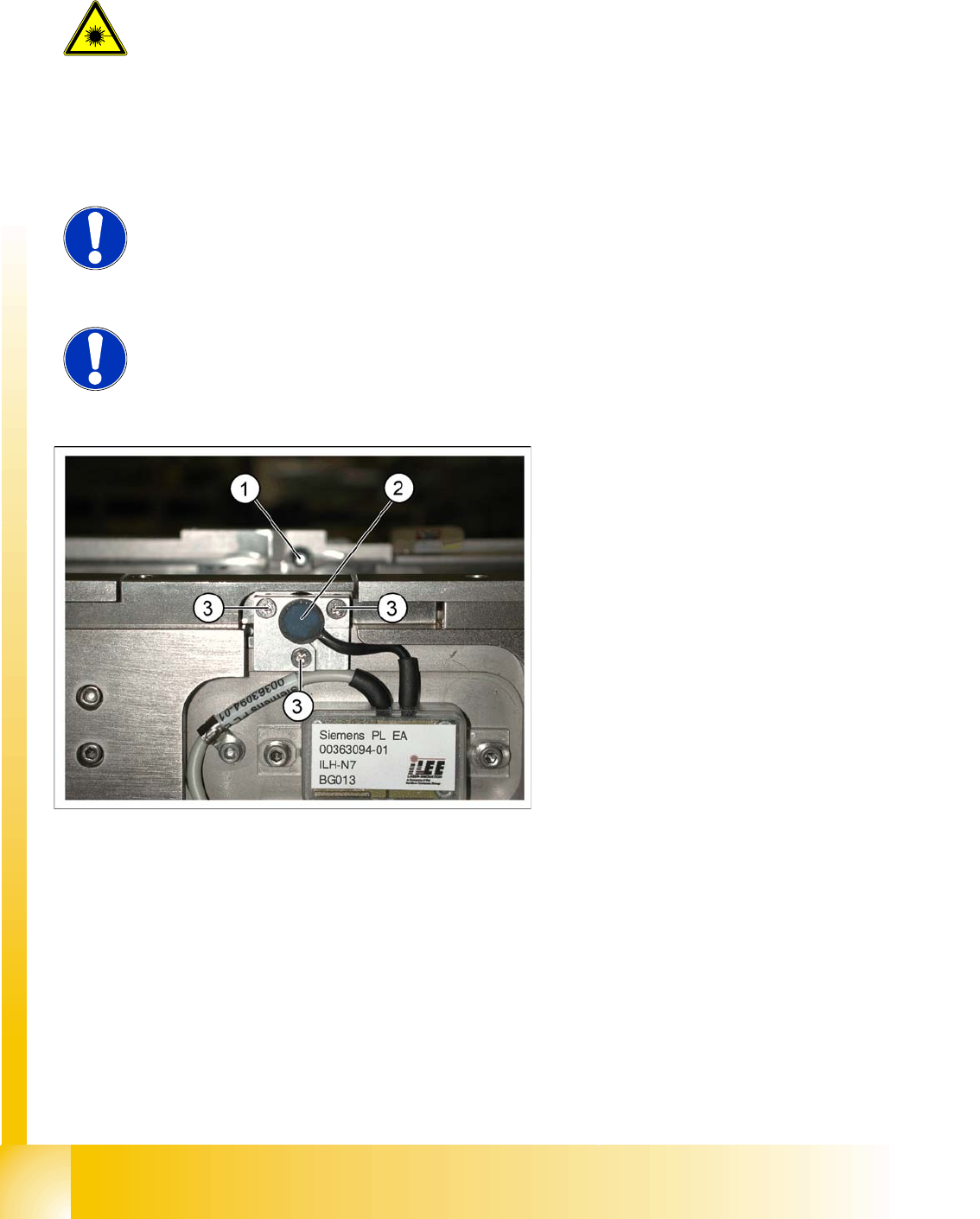
11.3.6 Setting and checking the laser light barrier for the stopper position
DANGER: Laser class 2
The laser light barrier transmitter emits class 2 laser beams. You do not need
to take additional protective measures!
X You should never look into the laser beam, however.
X Do the adjustment of the LASER Diode Beam direction only from the rear
side of the LASER (left machine side). Keep right side machine covers
closed!
NOTE:
The laser beam deflection has greatest effect at the maximum conveyor width,
it should always be calibrated at the maximum conveyor width.
NOTE:
After setting the laser light barrier you must check or re-teach the PCB
reference corner!
Legend:
1. Laser receiver
2. Laser diode
3. Setting screws (3x)
Modular conveyor
Setting and checking the laser light barrier for the stopper position Conveyor Settings
Student Guide SIPLACE D4 (FSE)
EN 09/2006 Modular conveyor
269
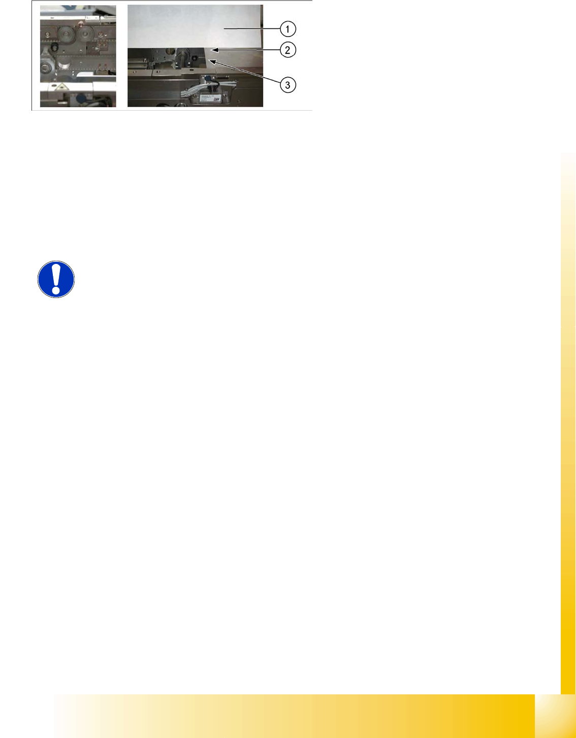
Procedure
X Set the maximum conveyor width.
X Choose General functions --> Cycle mode --> Safety mode switch on.
X Activate the relevant laser diode using the input/output functions in SITEST.
X Check the path of the laser beam by covering the front edge of a board with a white label and moving
it into the placement area.
X With the help of the three setting screws, adjust the laser beam to the center of the receiver.
X Check the PCB reference corner and reteach, if necessary.
Legend:
1. Paper
2. Visible laser beam
3. Board parallel to laser beam
NOTE:
When you move the paper, the beam must follow along the edge of the PCB as
accurately as possible, with minimal deflection to the left and right.