00195193-02 SG D4 FSE en (1).pdf - 第191页
Gantry Travel Ranges and Speed Monitoring at the D4 Settings Student Guide SIPLACE D4 (FSE) EN 09/2006 Gantry 177 8.2 Settings 8.2.1 T ravel Ranges and Sp eed Monitoring at the D4 The travel range of the X- and Y- axes i…
Gantry
Overview Pneumatic connectors on the gantry
Student Guide SIPLACE D4 (FSE)
Gantry EN 09/2006
176
Monitoring the position
Monitoring the track signals (counter edge spacing)
Monitoring the position to the hardware end switches, in accordance with the speed)
Monitoring the two Y axes in one placement area
Additionally each axis has a mechanical end stop (elastomer bumper).
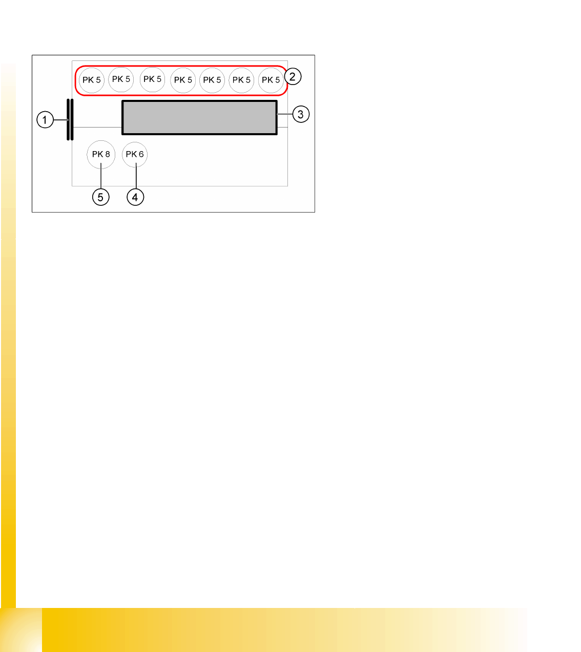
8.1.2 Pneumatic connectors on the gantry
The placement head is supplied with 4.5 bar compressed air from the pneumatic unit. The 7-fold
pneumatic hose is also used to cool the Y-axis motor. The X-axis motor is cooled by the traverse fan.
Legend:
1. Input: Discharged air Venturi nozzle
pneumatic hose (PK12)
2. Input: 7-fold pneumatic hose (PK 5)
3. Silencer for discharged air
4. Compressed air for the pickup / placement
circuit
5. Compressed air for the hold circuit
Gantry
Travel Ranges and Speed Monitoring at the D4 Settings
Student Guide SIPLACE D4 (FSE)
EN 09/2006 Gantry
177
8.2 Settings
8.2.1 Travel Ranges and Speed Monitoring at the D4
The travel range of the X- and Y-axes is determined automatically with the Sitest program.
This means that, during travel range calibration, the axis concerned moves as far as possible towards
the minimum or maximum position, until the set target value is no longer reached by the axis card. It is
then assumed that the hardware end position switch (bumper) has been reached. In a time window of
approx. 10 ms, the greatest actual value achieved is taken to calculate the travel range.
To guarantee an appropriate safety distance before the hardware end switch is touched, a certain
distance is deducted from the set travel range. This enables the axis to brake in time, even when errors
occur.
The end of the X-axis travel range is + or - 0.5
mm before the software end switch, which is itself
1.5mm before the bumper. A safety distance of 2.0
mm to the bumper is adequate, if the X-axis moves
into this area with excessive speed.
.The end of the Y-axis travel range is + or - 2.0
mm before the software end switch . The Y-axis
travel range for a particular placement area is
monitored in one direction by the software end
switch and a bumper. In the other direction, there
is a permanent exchange of communication
between the axes and their positions, via the SPI
Bus (see description of the anticrash function).
Gantry
Settings Travel Ranges and Speed Monitoring at the D4
Student Guide SIPLACE D4 (FSE)
Gantry EN 09/2006
178
1. This means that, during travel range
calibration, the X-axis moves as far as
possible towards the minimum or maximum
position, until it touches the bumper.
The travel ranges are calculated, taking into
account the relevant safety distance.
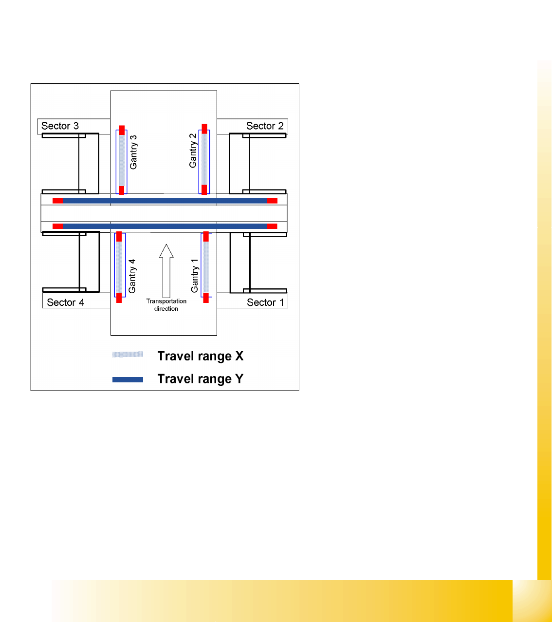
2. In placement areas 1 and 2, gantry 1/3 moves
to the minimum position and gantry 4/2 to the
maximum position, for calculation of the Y-axis
travel range .
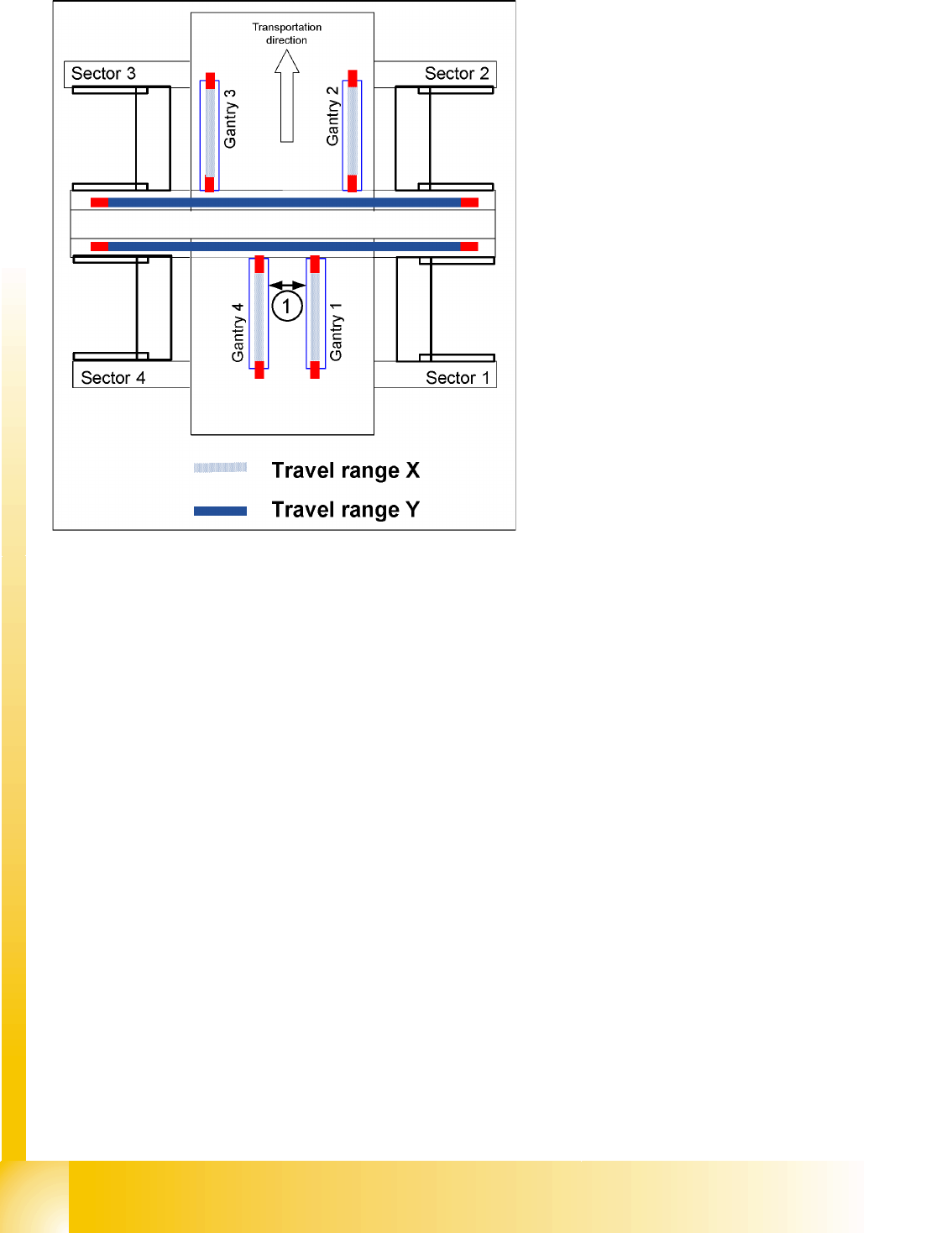
3. The minimum safety distance between the
gantries, during placement:minimum 4mm.