00195193-02 SG D4 FSE en (1).pdf - 第264页
Component handling Carrying out a walk-through inspection S Feeders Student Guide SIPLACE D4 (FSE) EN 09/2006 Component handling 249 separating plate will be offset or bent. 10.4.1.5 Using spindles for large t ape reels …
Component handling
S Feeders Carrying out a walk-through inspection
Student Guide SIPLACE D4 (FSE)
Component handling EN 09/2006
248
10.4 S Feeders
10.4.1 Carrying out a walk-through inspection
10.4.1.1 Checking the S feeder modules
X Check to ensure that the pick-up window on combination feeder modules (24/32 mm) is the right size
for the component.
X Check to see whether tape guides are inserted on combination feeder modules (24 mm / 32 mm).
10.4.1.2 Splicing the tape in good time
10.4.1.3 Checking the PCB supports
X Check the position of the magnetic PCB supports on the lifting table:
X Make sure that the PCB supports do not collide with components on the underside of the PCBs.
X In addition, make sure that the PCB supports do not collide with the PCB conveyor panels.
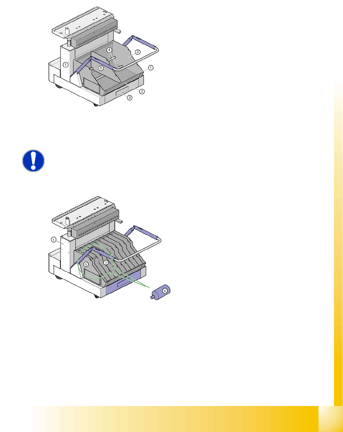
10.4.1.4 Inserting separating plates in the tape container
X Insert the separating plates as shown and remember that the smallest division of the tape container
is a 2x division. This will help avoid placement errors.
X Check that the separating plates engage in the same positions on both guide rails. Otherwise the
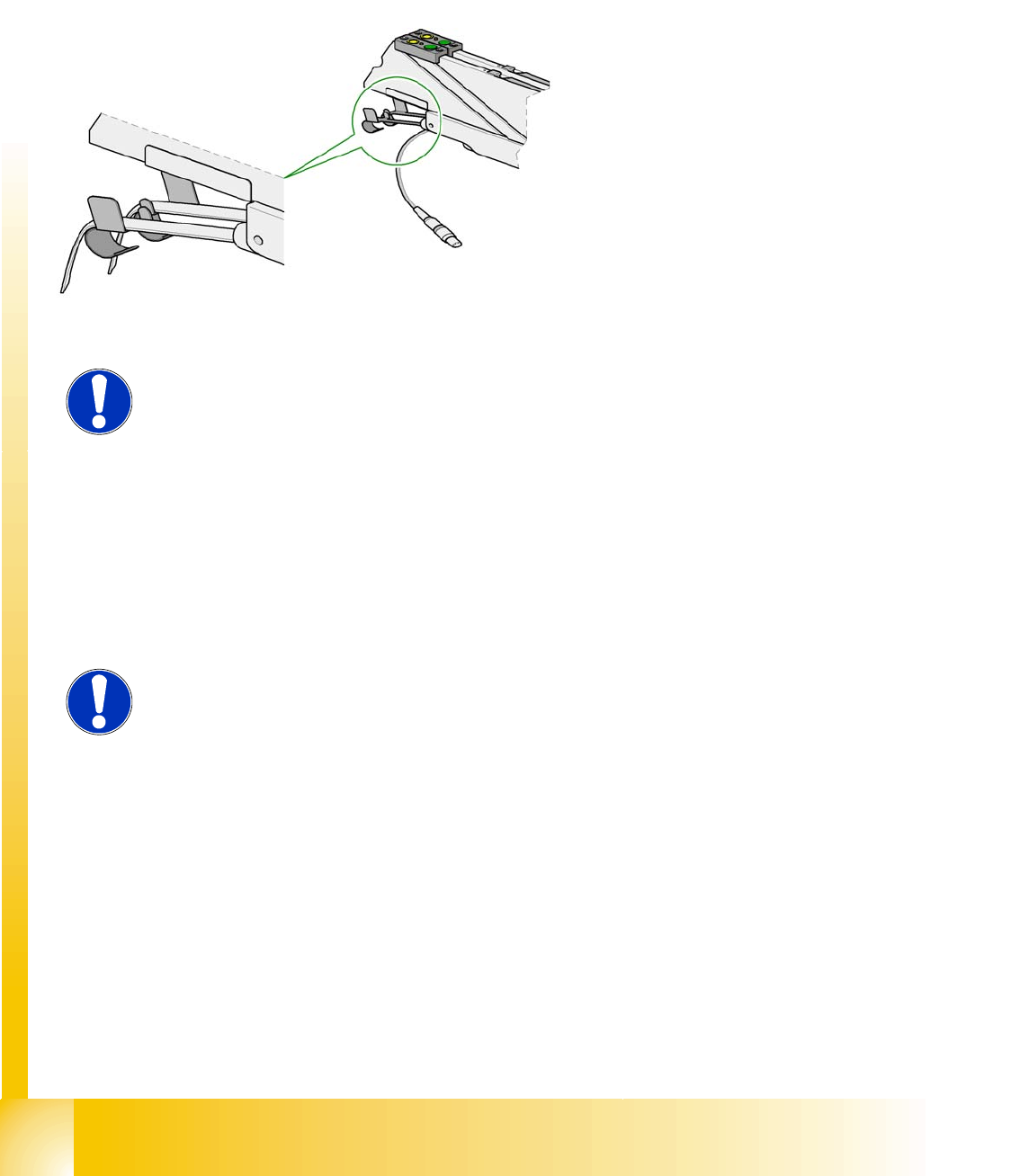
X Make sure that the tape is correctly placed in
the springs of the S feeder module.
X Check to see whether the tape foil removal
container for the S feeder module is full.
If it is full, then pull out the foil and cut it off with
scissors.
NOTE:
Tearing the foil instead of cutting it can lead to problems with the tape removal
mechanism.
For this reason the 3 x 8 mm feeder modules are fitted with an integral cutter.
This is in the tape foil removal container at the end of the feeder module under
the flaps.
NOTE:
Splice the tapes early enough so that the feeder modules do not run out of
components. Otherwise you will experience prolonged down times.
However, do not splice the tapes too early because if you wind the end of the
old tape onto the new reel after splicing, the reel holding the new tape may
become overfilled and the tape will slip off the reel and become tangled up. This
will again result in pick-up errors and prolonged down times.
Component handling
Carrying out a walk-through inspection S Feeders
Student Guide SIPLACE D4 (FSE)
EN 09/2006 Component handling
249
separating plate will be offset or bent.
10.4.1.5 Using spindles for large tape reels
X Insert spindles into the separating plates when using large tape reels.
1. Guide rail for the separating plates
2. Tape container
3. Waste tape container
4. support bars for the separating plates
5. separating plate
NOTE: using spindles
We recommend that you use spindles if the tape reel diameter exceeds 15"
(381 mm)". This will ensure that the feeder modules operate reliably.
1. Component trolley
2. position of the spindles
3. separating plate
4. Spindle (enlarged)
Component handling
S Feeders Setting up the feeder modules
Student Guide SIPLACE D4 (FSE)
Component handling EN 09/2006
250
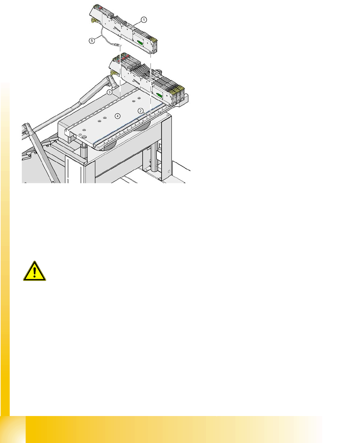
10.4.2 Setting up the feeder modules
10.4.2.1 Preparing the component feeder table and S feeder modules for set-up
X Clean the contact surface for the feeder module.
X Clean the contact surface on the component feeder table.
X Remove loose components from the component feeder table with a brush or use a vacuum cleaner
with appropriate nozzle.
X Remove any firmly attached components with the screwdriver.
1. S feeder module
2. centering pin
3. centering ball
4. component table
5. connecting cable for the S feeder module
CAUTION:
Avoid removing components from the component table with your fingers. You
may hurt yourself with tiny splinters of metal.