00195193-02 SG D4 FSE en (1).pdf - 第215页
C&P12 Placement Head Placement Procedure CO Recognition of Co mponent at Segment 1 in the CO Sensor S tudent Guide SIPLACE D4 (FSE) C&P12 Placement Head EN 09/2006 200 9.2.12 CO Recognition of Component at Segmen…
C&P12 Placement Head
Picking Up Component 8 Placement Procedure
Student Guide SIPLACE D4 (FSE)
EN 09/2006 C&P12 Placement Head
199
9.2.10 Picking Up Component 8
9.2.11 Picking Up Component 9
Star position 210°
Vision system: component at segment 2 of this
gantry is centered
DP station rotation of nozzle 12 to its pickup
angle
Pickup and placement station pick up the 8th
component
Component sensor during the next star step,
the nozzle length is measured at segment 10.
Star position 240°
Vision system: optical centering of component
3
DP station rotation of component 1 into its
exact placement angle
Pickup and placement station pick up the 9th
component
Component sensor during the next star step,
the nozzle length is measured at segment 11.
The process continues with the remaining
components: pickup, center and rotate into the
corrected placement angle.
C&P12 Placement Head
Placement Procedure CO Recognition of Component at Segment 1 in the CO Sensor
Student Guide SIPLACE D4 (FSE)
C&P12 Placement Head EN 09/2006
200
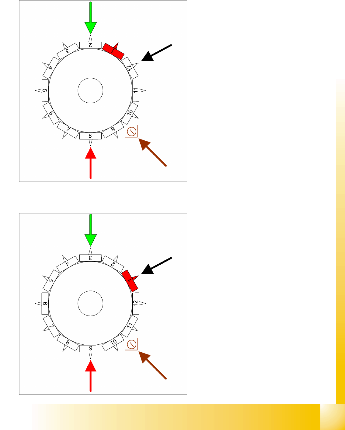
9.2.12 CO Recognition of Component at Segment 1 in the CO Sensor
9.2.13 Picking Up Component 12
Star rotates -> 330°
Measurement by the CO sensor (optional): While
the star axis rotates into position 330.000 digits:
the CO sensor checks the presence or the CO
height at segment 1.
The length measured before placement must
exceed nozzle length + CO height - CO height
tolerance.
Measurement is performed "On the Fly".
Star position 330°
Vision system: optical centering of component
6
DP station rotation of component 4 into its
exact placement angle
Pickup and placement station pick up the 12th
component
Communication with the CO table: enable the
cutter
Component sensor during the next star step,
the CO presence/CO height is checked at
segment 2.
C&P12 Placement Head
Placing Component 1 Placement Procedure
Student Guide SIPLACE D4 (FSE)
EN 09/2006 C&P12 Placement Head
201
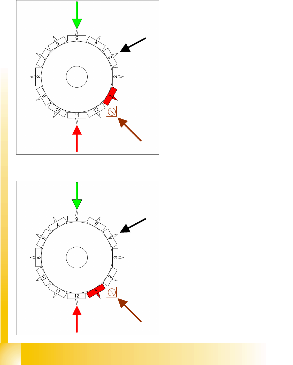
9.2.14 Placing Component 1
9.2.15 Placing Component 6
Star position 0°
Vision system: optical centering of component
7
DP station rotation of component 5 into its
exact placement angle
Pickup and placement station place
component 1
Component sensor during the next star step,
the CO presence/CO height is checked at
segment 3.
This procedure continues for the remaining
nozzles.
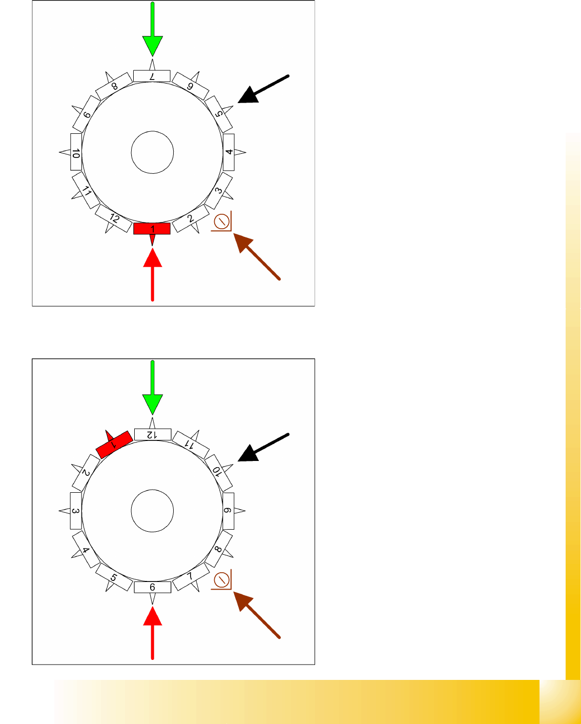
Star position 150°
Vision system: optical centering of component
12
DP station rotation of component 10 into its
exact placement angle
Pickup and placement station place
component 6
Component sensor during the next star step,
the CO presence/CO height is checked at
segment 8.