00195193-02 SG D4 FSE en (1).pdf - 第210页
C&P12 Placement Head Board Position Recognition and Temperature Compensation Placement Procedure Student Guide SIPLACE D4 (FSE) EN 09/2006 C&P12 Placement Head 195 9.2.3 Board Position Recogniti on and T emperatu…
C&P12 Placement Head
Placement Procedure Working Position on Placement Head
Student Guide SIPLACE D4 (FSE)
C&P12 Placement Head EN 09/2006
194
9.2 Placement Procedure
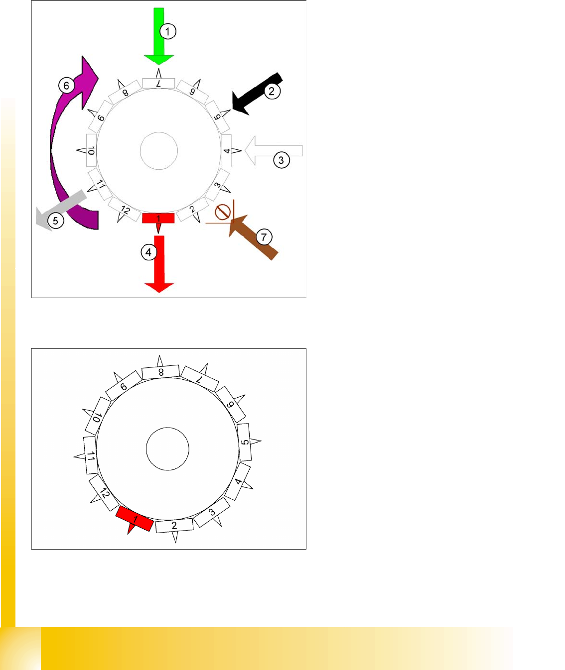
9.2.1 Working Position on Placement Head
9.2.2 C&P12 in Basic Setting Star 15°
Legend:
1. optical centering
2. Turning station / DLM2
3. Service position for segment: check/remove
the nozzles and sleeves
4. Pickup and placement station
5. Reject position D-machines
6. Direction of operation
7. Position of CO sensor option
Star position:
Digits: 15000
Angle 15°
1° is equal to 1000 digits
This is the basic C&P12 setting. When the X and
Y axes are in the waiting position, the star axis is
rotated into this basic setting.
C&P12 Placement Head
Board Position Recognition and Temperature Compensation Placement Procedure
Student Guide SIPLACE D4 (FSE)
EN 09/2006 C&P12 Placement Head
195
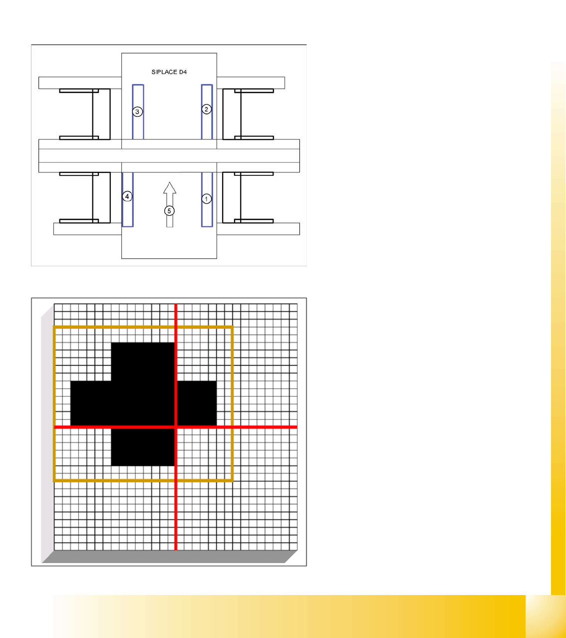
9.2.3 Board Position Recognition and Temperature Compensation
Board position recognition is used to determine the exact position of the board in the machine (conveyor
--> placement area). There should be at least two fiducials on the board. These are then used to
calculated the X/Y position and the rotary angle of the board, in the conveyor system. The fiducials
should not be on the same line as one another. A maximum of 3 fiducials can be programmed for position
recognition. In addition to determining the position of the board in the conveyor system, this 3rd fiducial
enables you to determine and correct any displacement within the board (jolted, stretched). In addition
to board recognition, SIPLACE D4 machines perform temperature compensation with the 2nd gantry in
the placement area. This compensates another error source which could affect accuracy.
Legend:
1. Gantry 1
2. Gantry 2
3. Gantry 3
4. Gantry 4
5. Transport direction
Gantry 4: position recognition with max. 3
fiducials,
Gantry 2: position recognition with max. 2
fiducials,
Gantries 1 and 3: temperature compensation by
approaching the fiducials (position difference
compared to gantry 4 or 2)
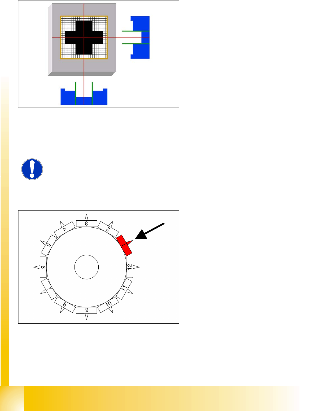
A fiducial is expected at this target position. The
PCB camera moves out of the waiting position to
this fiducial position.
Board recognition is performed before the 1st
component is taken up.
The gantry axes move the PCB camera to the
theoretical fiducial position. The camera
records an image of the 1st fiducial. The Vision
system calculates the center position.
C&P12 Placement Head
Placement Procedure Board Recognition - Centering the Board Fiducials
Student Guide SIPLACE D4 (FSE)
C&P12 Placement Head EN 09/2006
196
9.2.4 Board Recognition - Centering the Board Fiducials
9.2.5 Preparing Nozzle 1 - Moving to Pickup Angle (0° or 90°)
The centered fiducial now defines the actual
position of the board.
The camera records an image of the 2nd
fiducial and the Vision system calculates the
center position of this image.
Another calculation determines the deviation
between the target and the calculated fiducial
position.
All board fiducials are optically centered using
this procedure.
The data is sent to the machine control
system.
Corrected values are now calculated for the
X,Y and angular position of the board.
The gantry axes now move the placement
head to the first pickup position.
NOTE: Synthetic fiducials
If synthetic fiducials are used, the procedure described above remains the
same but inkspot recognition is then performed after fiducial recognition.
The star axis rotates to 240°. Nozzle 1 is now
in the DP station.
The DP station swivels in and the DP axis
control system rotates the nozzle to its pickup
angle of 0° or 90° (default pickup angle).
As soon as the nozzle reaches its position, an
end position signal is emitted and the DP
station swivels back.
The other nozzles on the head are then moved
into their pickup angles by further rotation of the
star.