00195193-02 SG D4 FSE en (1).pdf - 第320页
Sitest Nozzle Changer (C&P head) Basic description of all calibration steps Student Guide SIPLACE D4 (FSE) EN 09/2006 Sitest 301 This sequence is repea ted. From the 8 placemen t positions is the a verage value of th…
Sitest
Basic description of all calibration steps Component camera
Student Guide SIPLACE D4 (FSE)
Sitest EN 09/2006
300
PCB Camera - CO Camera Offset:
During measurement of the segment offset up (I), the calibration of the PCB camera -> CO camera
offset is performed with segment 1:
The distance in X- and Y- direction of the camera centers is determined in µm.
The top segment offset (I) is compared to a calculated average value. (the segment offset I of
segment 1 is therefore no longer 0.)
Segment 1 is the reference point for calculation of the offset (I and II).
This distance is saved in REAL.MA at ‘Kopfoffsets’ at Kopf 1 Kopfoffset_X /..Y. The segment offset
down (II) for segment 1 is 0 (see below).
The segment offsets for the remaining 11 segments are saved in the PIP_OFF.MA file (as deviation
to segment 1).
Deviation in the X and Y direction of the rotary axis for the remaining segments, compared to
segment 1 (in µm).
Measurement is performed at 0° and 180° or 90° and 270° in each case. The center of the segment
is then determined from these 0/180° or 90/270° values.
The values for the segment offset are saved in the PIP_OFF.MA file.
Sequence segment offset bottom (II):
12.3 - 2: Sequence at one nozzle:
After the segment offset up (I) calibration step has been performed, the calibration procedure for the
segment offset down (II) begins for C&P DLM 3:
Is the calibration tool picked with a Nozzle under 0 degree; optically centered and placed with the
PCB-camera is the exact placement position determined (in µm).
Is the calibration tool picked with a Nozzle under 90 degree; optically centered and placed with the
PCB-camera is the exact placement position determined (in µm).
Is the calibration tool picked with a Nozzle under 180 degree; placed with the PCB-camera is the
exact placement position determined (in µm).
Is the calibration tool picked with a Nozzle under 270 degree; placed with the PCB-camera is the
exact placement position determined (in µm).
ATTENTION:
For the segment offset I (top), the standard deviation value should not exceed
600 µm. The difference between the segments must not exceed +/- 150 µm.
Segment offset II (down) absolute threshold +/- 150 µm and difference in values
max. +/- 150 µm.
NOTE:
The segment offset II (bottom), from the first segment is always 0 that is the
reference value to the other segments.

Sitest
Nozzle Changer (C&P head) Basic description of all calibration steps
Student Guide SIPLACE D4 (FSE)
EN 09/2006 Sitest
301
This sequence is repeated. From the 8 placement positions is the average value of the place.
Deviation calculated and taken for the seg. offset.
12.3.6 Nozzle Changer (C&P head)
Each nozzle magazine has an fiducial which will recognize during the calibration procedure at first.
optional, calibrate the pick up height from the nozzle changer.
optional, calibrate the reject position from the nozzle changer, necessary to reject nozzle which are
defekt.
12.3.7 Calibrate and teach machine positions
New function for calibrate the positions is the teach menu before calibrate, so that you can teach the
correct position for a successfull calibration.
12.3.7.1 Conveyor sides
This new calibration procedure is necessary for the modular conveyor system.
With the modular conveyor are all conveyor sides adjustable. For adjustment the conveyor sides we use
one stepper motor which is connected via a toothed belt to the driver unit. The position of the conveyor
side is recognized by a proximity switch, meaning that there is a switching point for each conveyor side.
With this calibration the switch points are optimized of the entire travel range of the width adjustment.
Calibration is required to ensure that the two adjustment drives move the conveyor sides parallel to one
another.
Automatically Sequence (Transport mapping):
Initialize the driver unit, move to the right side (limit switch)
Driver unit recognize the fixed conveyor side (sides dual conveyor) move the conveyor sides a
standard position of 55mm.
The driver unit moves the conveyor side(s) step-by-step (10 mm steps) and determines the offset of
the switching points for the two driver units in the various conveyor side positions.
This calibration of the side position will be done for width adjustment wider and smaller.
The results are saved in the conveyor controller as correction values and taken into account later
when setting and measuring the conveyor width.
12.3.7.2 Conveyor width calibration
The conveyor width offset can be determined by using a board with a width of your choice. This width
must be entered by the operator. This ensures that a consistent predefined tolerance (offset) is used
between the conveyor sides, for the various different conveyor widths, thus preventing the boards from
getting jammed.
ATTENTION:
Before starting calibration of the nozzle changer, check the nozzle changer
configuration and the component level.
NOTE:
Calibration needs to be performed for lanes 1 and 2.
Sitest
Basic description of all calibration steps PCB mapping
Student Guide SIPLACE D4 (FSE)
Sitest EN 09/2006
302
12.3.7.3 PCB fixed corner
X Select gantry 1 or 2.
X Select PCB reference corner position right or PCB reference corner position left (dual conveyor)
X Moves the active gantry with the PCB camera over the reference corner position and switches the
screen display to the PCB camera for checking purposes. The reference corner position is visible in
the camera's field of view. Teach the gantry at the top right edge of the board, so that the PCB
reference corner is in the center of the camera's field of vision. (see Section 12.2.8 Calibrate the PCB
reference corner [J 293]).
X This board reference corner determines the coordinate source for the programmed placement
position, fiducial position and inkspots in the machine.
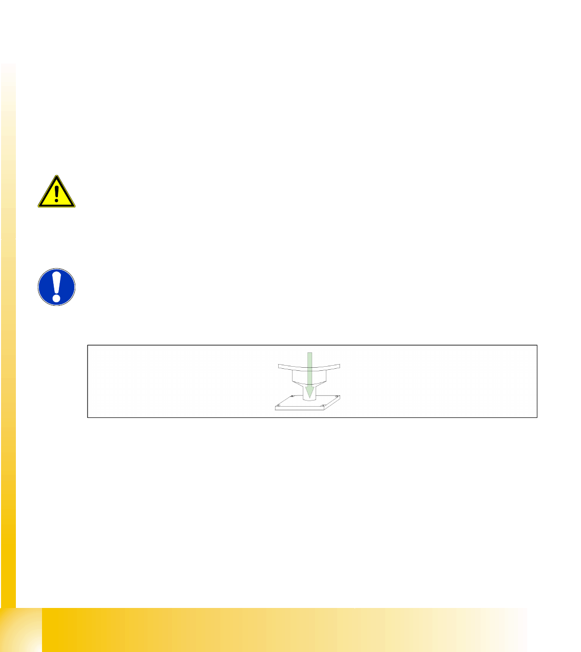
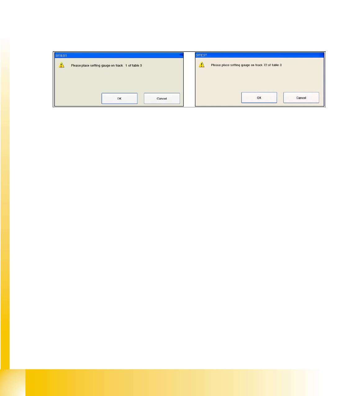
12.3.7.4 Pickup Position (Calibrate the Component Table Track 1- 72)
Determines the X and Y positions for tables 1 to 4 with the reference tracks 1 and 72.
12.3 - 3: Calibrate the Component table
12.3.8 PCB mapping
With the PCB mapping the linearity of the X- and Y-guidance for PCB-camera movement is measured
in the placement area. The PCB-camera center the cross fiducials on a high precise glass plate. This
mapping plate has been measured with a measuring device and the dimensions are taken into account
during the mapping procedure.
12.3.8.1 Preparation for Mapping
X At the single conveyor the SITEST move the transport sides to 508mm wide the mapping plate is 90
degree turned.
X At dual conveyor the SITEST SW move all the conveyor sides depend of the conveyer which is
selected the conveyor for mapping to 450 mm wide the other track to 0mm. This enables you to use
the dual conveyor as single conveyor. The Mapping must be carried out for the maximum conveyor
width.
X To prepare the board and RV mapping procedure, the SITEST SW automatically sets the conveyor
sides, so that the mapping plate fits into the relevant conveyor side.
X The C&P12 must be equipped with nozzle type 956.
X The calibration tools are in the calibration pocket.