00195193-02 SG D4 FSE en (1).pdf - 第158页
Axis dynamic Servo amplifier TBS .. and SDS ... Axis dynamic basics Student Guide SIPLACE D4 (FSE) EN 09/2006 Axis dynamic 145 7.3 Axis dynamic basics Each axis starts from a position with acceleration a constant speed p…
Axis dynamic
Parts for the axis control Servo amplifier TBS .. and SDS ...
Student Guide SIPLACE D4 (FSE)
Axis dynamic EN 09/2006
144
7.2.2 Servo amplifier TBS .. and SDS ...
Servo amplifiers of type TBS are used for the X/Y and star axes, while SDS servo amplifiers are used
for the Z and DP axes.
7.2 - 2: Servo amplifier
This SDS and TBS Servo amplifiers are to reset by Servo disable / Servo enable at Axis controller board.
All servos are individually set for the maximum motor current of the drive unit connected. This means the
servo amplifiers have to be mounted specifically for the current axis type.
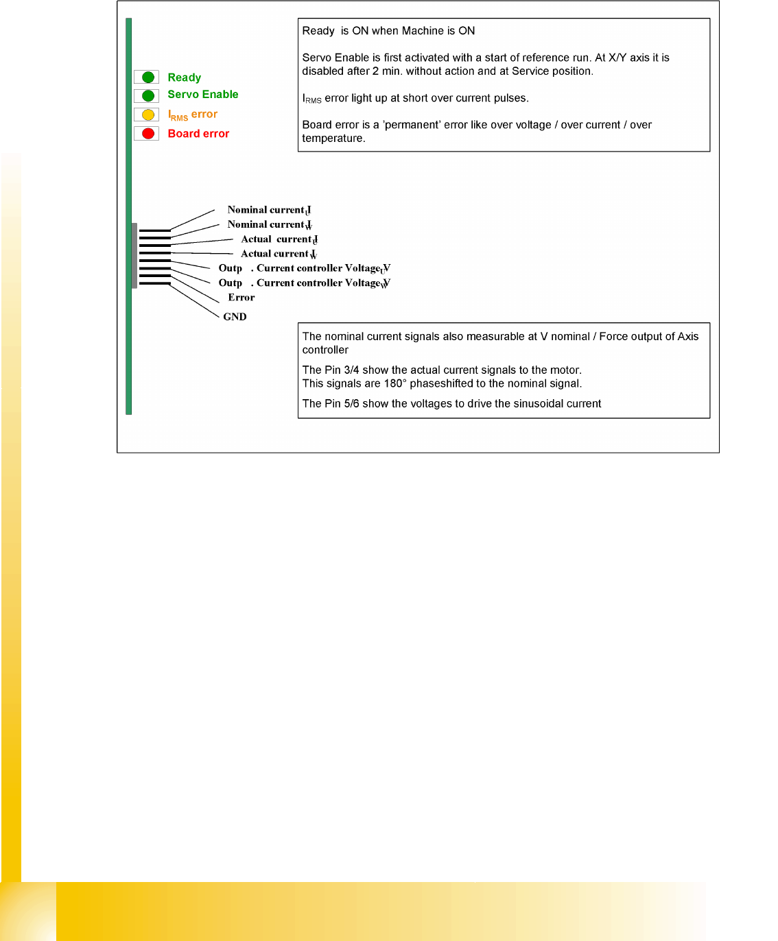
Measurement Pin MP7:
In case of an error on the Servo amplifier, it is possible to measure on the analog output pin MP7 different
voltages to determined the error.
Overvoltage -1 V
Overcurrent -2 V
Overtemperature -3 V
Nominal current exceeded -4 V
Axis dynamic
Servo amplifier TBS .. and SDS ... Axis dynamic basics
Student Guide SIPLACE D4 (FSE)
EN 09/2006 Axis dynamic
145
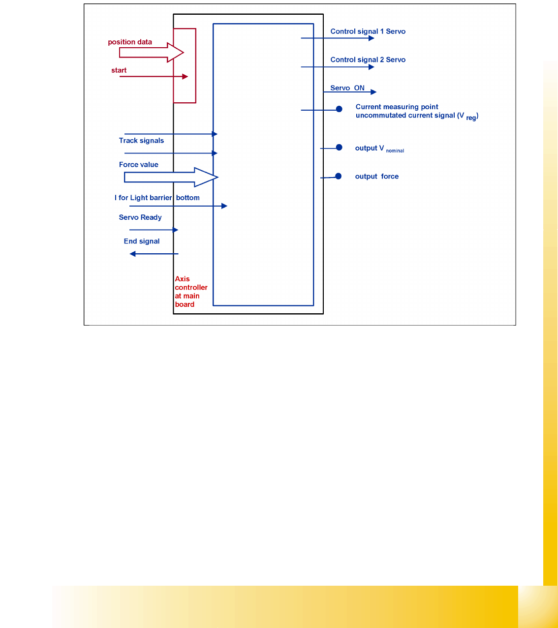
7.3 Axis dynamic basics
Each axis starts from a position with acceleration a constant speed phase and deceleration should move
the axis into a target position. The dynamic movement of the axis on the SIPLACE machine is regulated
by a digital control system. A powerful digital processor permanently adjusts the axis behavior to each
state of axis dynamic. This means, that all adjustments for speed (Tacho) and positioning quality (P-gain)
on the servo amplifier are removed. The control signals are different for this new axis control principle.
7.3 - 1: Digitally controlled axes for SIPLACE machine
Axis dynamic
Axis dynamic basics Servo amplifier TBS .. and SDS ...
Student Guide SIPLACE D4 (FSE)
Axis dynamic EN 09/2006
146
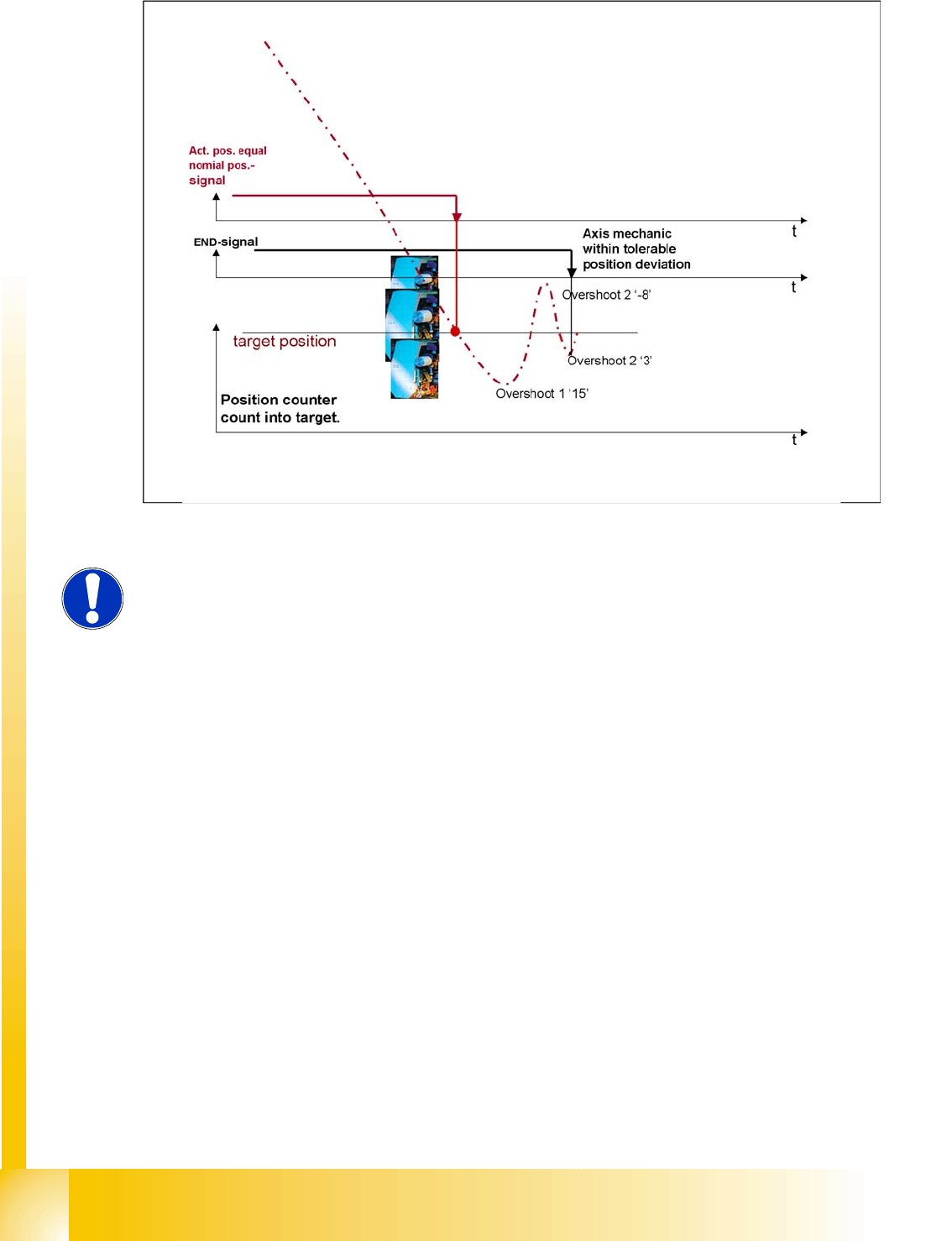
7.3 - 2: Positioning with overshoot into target position
During initial positioning into the target position, the actual equals target position signal triggers an
overshoot count in the axis test box (SAT) for calculation of the position deviation signal.
The known ’V nominal ’ speed signal and the ’force’ force limit signal are replaced by motor phase
nominal current signals to the DC respective AC Drive.
NOTE:
The position deviation signal shows the positioning quality of an axis movement
in position.