00195193-02 SG D4 FSE en (1).pdf - 第77页
Communication and Control CAN Bus Machine Controller Communication S tudent Guide SIPLACE D4 (FSE) Communication and Control EN 09/2006 76 wiring is replaced by one serial bus Each mo dule is given a CAN Bus connection. …
Communication and Control
Machine Controller Communication CAN Bus
Student Guide SIPLACE D4 (FSE)
EN 09/2006 Communication and Control
75
4.3 CAN Bus
The development of Controller Area Networks began as modern vehicles were controlled, monitored and
equipped with electronic controls and comfort features. Examples of such devices include engine
management systems, active suspension, ABS, gear control, lighting control, air conditioning, airbags
and central locking.
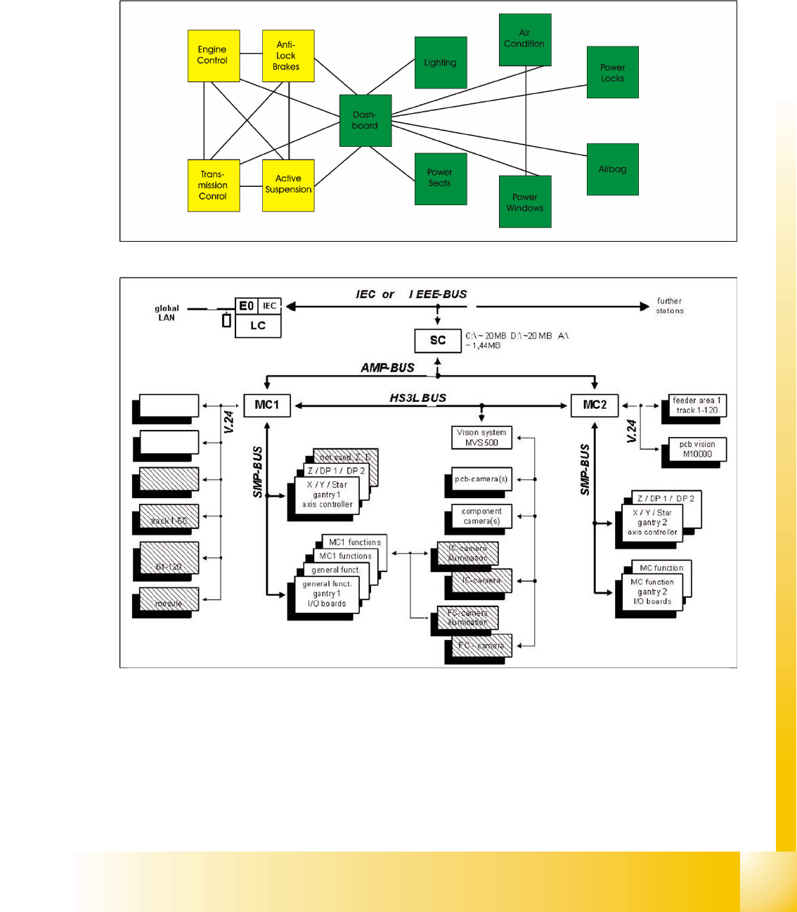
4.3 - 1: Communication via cable connection
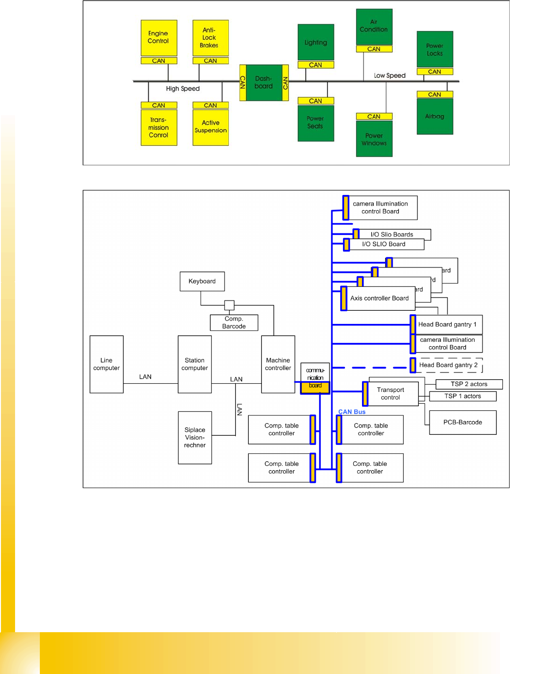
4.3 - 2: Communication e.g. on Siplace S15 machine
To improve the behavior of the vehicle even further, it was necessary for the different control systems
(and their sensors) to exchange information. This was usually done by discrete interconnection of the
different systems (i.e. point to point wiring). The requirement for information exchange has then grown
to such an extent that a cable network with a length of up to several miles and many connectors was
required. This produced growing problems concerning material cost, production time and reliability.
The solution to this problem was the connection of the control systems via a serial bus system. This bus
had to fulfill some special requirements due to its usage in a vehicle. With the use of CAN, point-to-point
Communication and Control
CAN Bus Machine Controller Communication
Student Guide SIPLACE D4 (FSE)
Communication and Control EN 09/2006
76
wiring is replaced by one serial bus Each module is given a CAN Bus connection. This is accomplished
by adding some CAN-specific hardware to each control unit that provides the ’rules’ or protocol for
transmitting- and receiving information via the bus.
4.3 - 3: Communication via CAN bus on example car controlling
4.3 - 4: Communication via CAN bus on example car controlling
Communication and Control
CAN Bus in General CAN Bus
Student Guide SIPLACE D4 (FSE)
EN 09/2006 Communication and Control
77
4.3.1 CAN Bus in General
CAN is a serial bus system especially suited for networking devices as well as sensors and actuators
within a system or subsystem. It has Multimaster features i.e. bus access can be started simultaneously
in multiple cases.
The CAN network does not consist of addressing individual components in the conventional sense but
instead involves sending prioritized messages to all subscribers (broadcasting). Each subscriber
decides on the basis of the identifier received whether it should process the message or not. The
identifier determines the priority that the message enjoys in competition for bus access. Programming is
comparatively easy, due to the simple CAN bus communication system.
Each CAN message can carry 0 to 8 Byte of user information. Of course, you can transmit longer data
information by using segmentation. The maximum transmission rate is specified as 1 Mbit/s. This value
applies to networks about 40 m. Greater distances reduce the transmission rate e.g. a length of 500 m
allows roughly 125 KBit/s or a length of 1 km would transport roughly 50 KBit/s.
The maximum bus speed is 1 MBit/s, which is achieved by a bus length of 40 m through the use of a
twisted-pair cable. For bus lengths longer than 40 meters the bus speed must be reduced. For a bus
length above 1000 meters special drivers should be used.
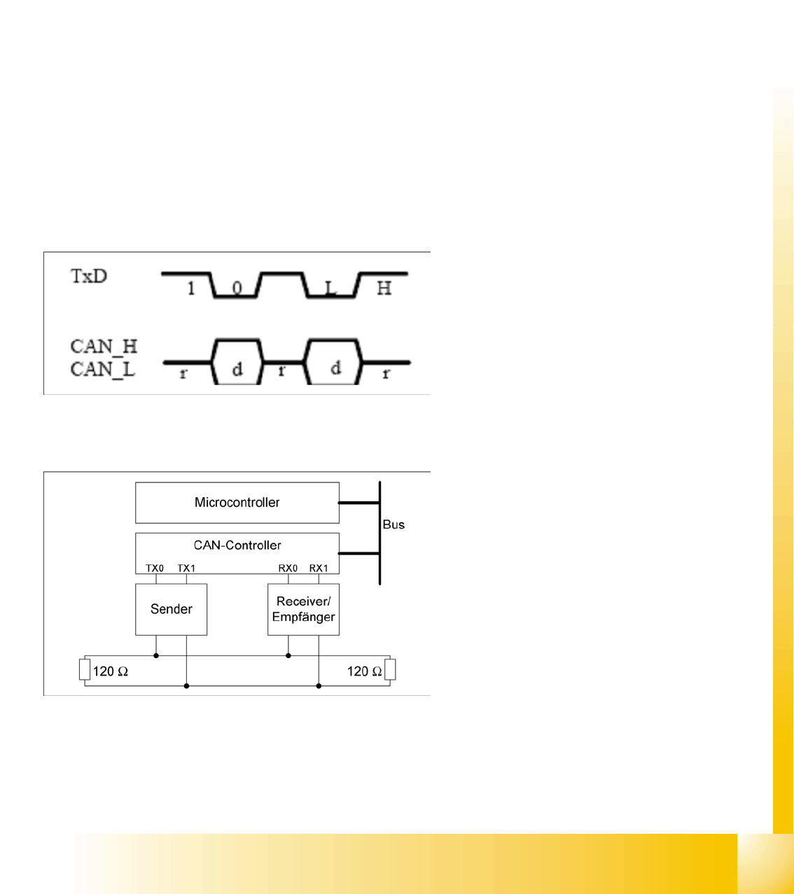
4.3.1.1 CAN Bus Structure
The CAN Bus consists of 2 lines (CAN_High,
CAN_Low). These are connected to a terminating
resistor with 120 Ohm at each end.
Each subscriber which is connected to the CAN
Bus, has a transmitter, a receiver and a CAN
controller.
This CAN controller communicates with the
microcontroller. Our SIPLACE machines use an 8
or 16 bit (TQM) processor.
Legend:
Microcontroller: exchanges data with the CAN
controller
CAN controller: adds the data frame,
establishes the connection, handles errors
and their corresponding solutions.
Transmitter/receiver: adjusts the level (driver
levels)