00195193-02 SG D4 FSE en (1).pdf - 第112页
Reference run X and Y commutation position search Reference Run Gantry Student Guide SIPLACE D4 (FSE) EN 09/2006 Reference run 105 5.2.2 X and Y commutation position search A commutation position search for the 3 phases …
Reference run
Reference Run Gantry Reference Run Sequence at X and Y-axis
Student Guide SIPLACE D4 (FSE)
Reference run EN 09/2006
104
5.2 Reference Run Gantry
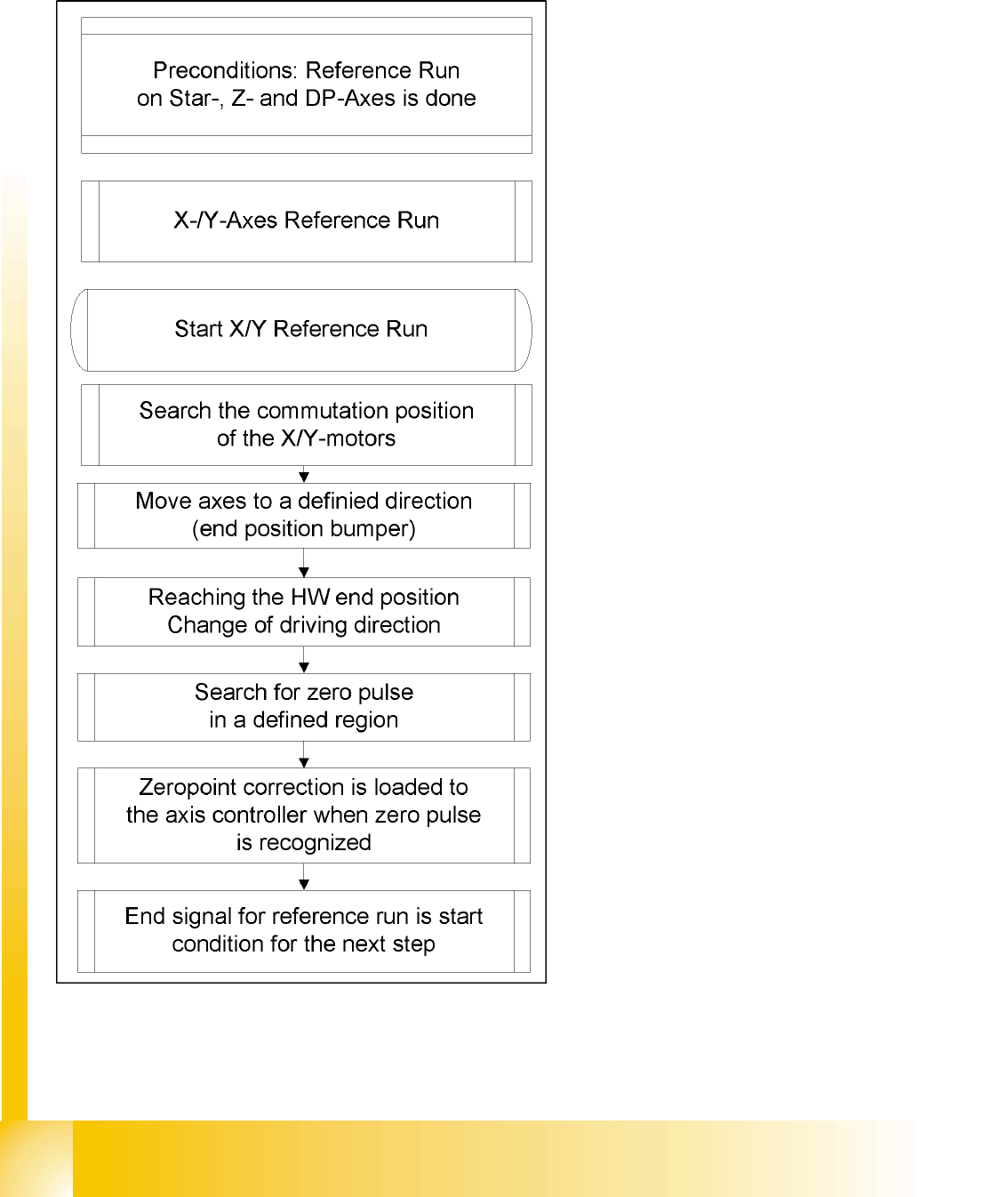
5.2.1 Reference Run Sequence at X and Y-axis
When performing a reference run with bumper
detection, proximity switch queries are no longer
used. Instead, the reference run continues until
the mechanical end stop (bumper) is reached. The
reference pulse is searched for in a set region of
the incremental scale.
The axis travel direction is reversed, if the set
target value is not reached by the axis(target value
≠ actual value). The zero pulse will then be
searched for in a set part of the incremental scale.
After reaching the zero pulse, the axis will stand in
a defined position.
Reference run
X and Y commutation position search Reference Run Gantry
Student Guide SIPLACE D4 (FSE)
EN 09/2006 Reference run
105
5.2.2 X and Y commutation position search
A commutation position search for the 3 phases AC-drives on the gantry starts right after the head axis
reference run is succesfully finished.
Starts reference run for main axes at all 4 gantries:
1. Reference motor commutation .
2. Referencing the measurement system.
After detecting the end position bumper, the axis searches for the zero pulse in a specific range . If
the axis detects several or no zero pulses, it will stop and an error message will be issued .
3. Approaching the zero point correction value
4. Reference run of main axes completed, height reference run starts
5.2.3 Reference run of X- and Y- axes
Starts reference run for main axes at all 4 gantries:
1. Commutating the motors
2. Referencing the measurement system.
After detecting the end position bumper, the axis searches for the zero pulse in a specific range . If
the axis detects several or no zero pulses, it will stop and an error message will be issued .
3. The axes are now in a defined position.
4. Reference run of main axes completed, height reference run starts
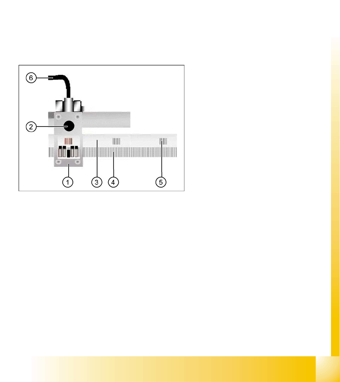
Legend:
1. Incremental encoder
2. Test plug for track signals (analog)
3. Incremental scale
4. Increments on the scale (1µm resolution)
5. Zero pulse
6. Connection cable to gantry distributor/gantry
head distributor
Reference run
Reference Run C&P12 Overview Head Reference Run
Student Guide SIPLACE D4 (FSE)
Reference run EN 09/2006
106
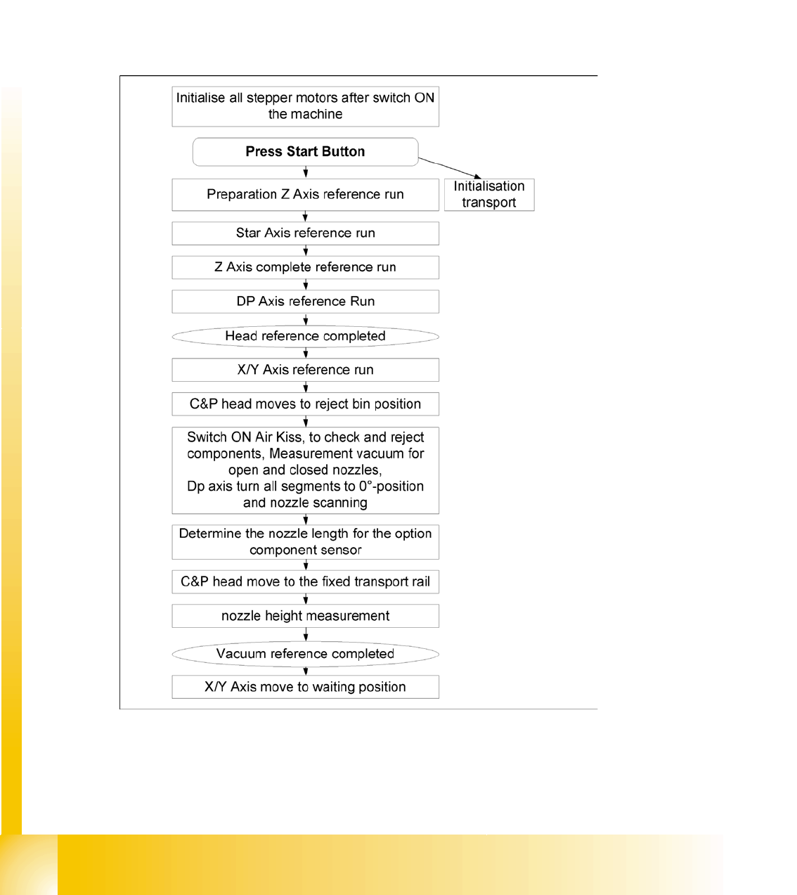
5.3 Reference Run C&P12
General procedure
The reference run procedure is identical to that for C&P12 type DLM3.
The reference run starts with the initialisation of all the head stepper motors. This allows then, the
head axis to reference by moving first to their zero pulses and then to their zero point correction
values.
In SIPLACE D4 machines, all heads and gantries move into the reference position at the same time.
5.3.1 Overview Head Reference Run
5.3 - 1: General reference run in detail