00195193-02 SG D4 FSE en (1).pdf - 第282页
Modular conveyor Conveyor Settings Width adjustment unit (Driver) S tudent Guide SIPLACE D4 (FSE) Modular conveyor EN 09/2006 266 1 1.3.4.1 Adjusting the limit switch for initialize the driver 1 1.3.5 Wid th adjustment u…
Modular conveyor
Checking the limit switch position Conveyor Settings
Student Guide SIPLACE D4 (FSE)
EN 09/2006 Modular conveyor
265
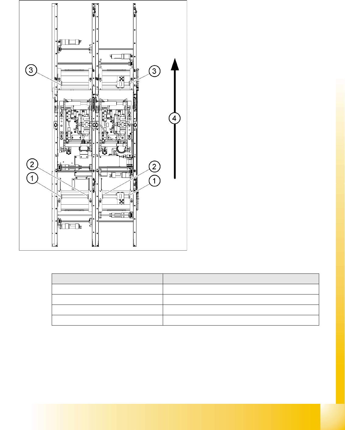
11.3.4 Checking the limit switch position
X Check the minimum and maximum width and ensure that the conveyor sides are parallel.
Legend:
1. Limit switch on the input conveyor - fitted
below the conveyor side
2. Limit switch on the input conveyor - fitted
below the conveyor side
3. Limit switch for the width adjustment unit
4. Transport direction
Limit switches on the input conveyor:
There are 5 limit switches below the conveyor
sides near the input conveyor. The limit switch
is designed to prevent the conveyor sides
hitting one another or the conveyor frame.
Limit switches on the output conveyor:
There are 2 limit switches for the driver near
the output conveyor. They serve to protect the
traveling range and initialize (right side) the
driver for the width adjustment.
Setup Value
Minimum width: 49.7 mm
Maximum width of single conveyor 508.5 mm
Maximum width of dual conveyor 216.5 mm (standard)
Maximum width of dual conveyor 242.5 mm (standard)
Adjustments
Modular conveyor
Conveyor Settings Width adjustment unit (Driver)
Student Guide SIPLACE D4 (FSE)
Modular conveyor EN 09/2006
266
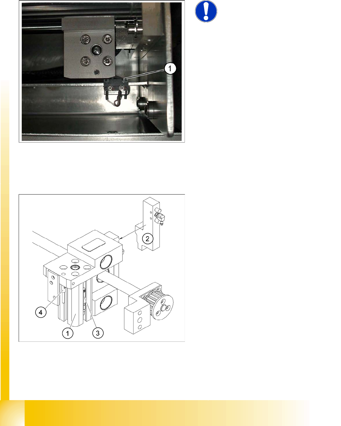
11.3.4.1 Adjusting the limit switch for initialize the driver
11.3.5 Width adjustment unit (Driver)
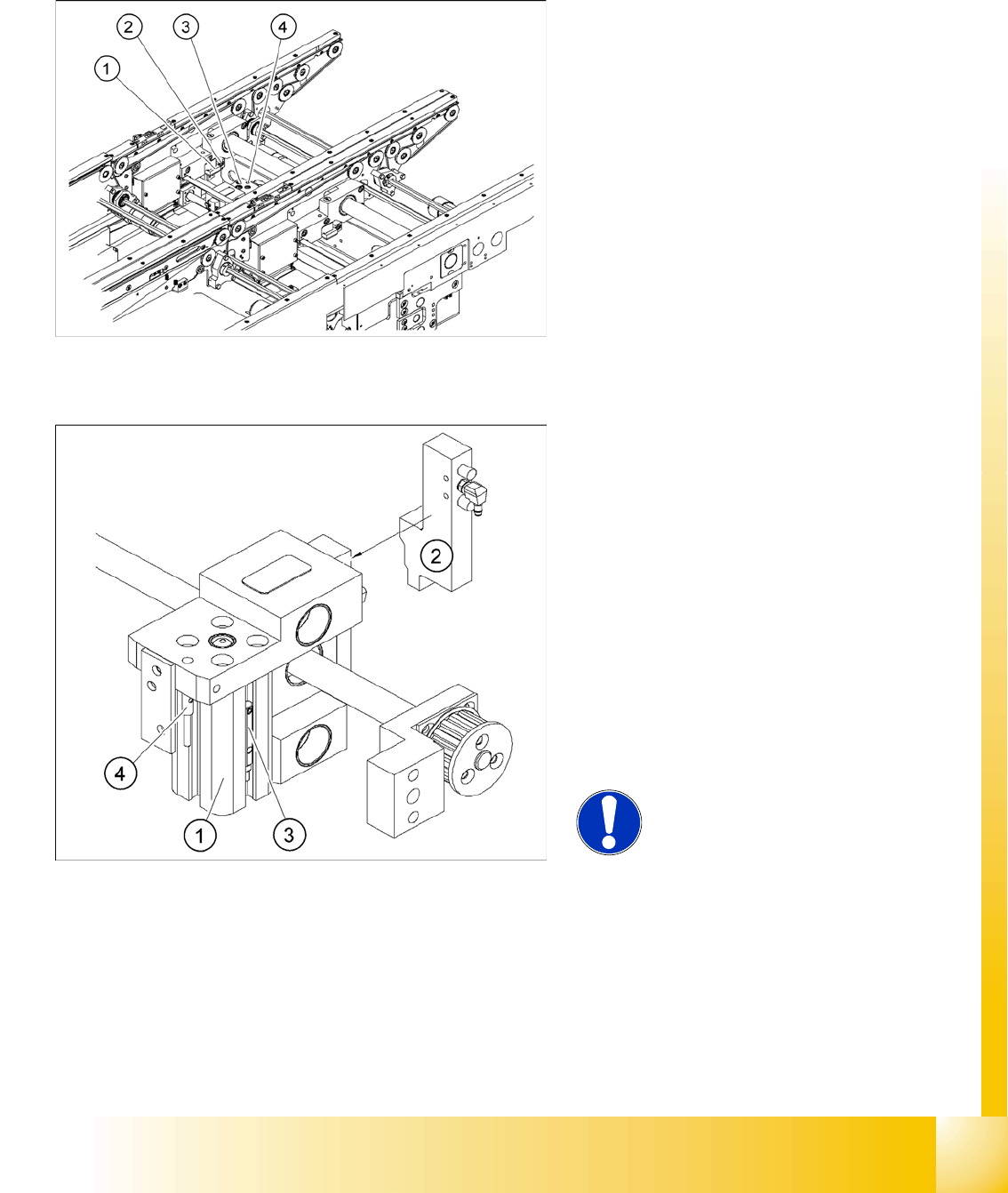
11.3.5.1 Setting the BERO on the driver
X When installing the proximity switch (4) , make sure that the proximity switch is level with the
adjustment unit housing.
X The switching point is set via the actuator on the conveyor side
X Move the driver under the conveyor side, then loosen the actuator using the screw.
NOTE:
This setting is only required after
replacing the switch or other error
functions in the width adjustment
reference run.
X Move the driver for the width adjustment by
hand (via the toothed belt) to the conveyor
side.
X Loosen the two screws on the limit switch (1).
X Move the limit switch in the slot towards the
driver and make sure, that the limit switch is
safely switched on.
X Check the switching state of the
corresponding LED (H11 for conveyor 201)
(H41 for conveyor 301) in the conveyor control
software.
X Fit the limit switch in this position.
X Calibrate the conveyor width via the SITEST
program.
Legend:
1. Pneumatic cylinder
2. Solenoid valve
3. Proximity switch for pneumatic cylinder (for
"locking pin up" recognition)
4. Proximity switch for adjustment unit(for
conveyor side recognition)
X The proximity switch (3) serves as a signal for
controlling the pneumatic valve of the
adjustment unit. Once the switching point
"conveyor side present" has been reached,
the conveyor side is connected via the
pneumatic valve.
Modular conveyor
Width adjustment unit (Driver) Conveyor Settings
Student Guide SIPLACE D4 (FSE)
EN 09/2006 Modular conveyor
267
X Place the driver at the final dimension of 2/10 mm, press the actuator onto the final dimension and
fix with the screw.
X Actuators on all conveyor sides have to be checked and maybe adjusted.
X
Calibrate the conveyor
with SITEST.
11.3.5.2 Setting the ’pneumatic cylinder BERO’ on the driver
X Start SITEST
X Set any conveyor width. The adjustment units are positioned directly under the conveyor side.
X Start the I/O menu.
X Activate the pneumatic cylinder.
X Set the proximity switch on the pneumatic cylinder so that the LED (H36/H37 TSP 301) (H64/65
TSP 201) shines when connected.
Legend:
1. Actuator
2. Actuator fixing screw
3. Driver
4. Proximity switch, adjustment unit
Legend:
1. Pneumatic cylinder
2. Solenoid valve
3. Proximity switch for pneumatic cylinder (for
"locking pin up" recognition)
4. Proximity switch for adjustment unit(for
conveyor side recognition)
The proximity switch (3) on the adjustment unit
cylinder should operate when the adjustment
unit pin is pushed out by the pneumatic
cylinder and therefore connected to the
conveyor side. This signal enables the width
adjustment motor.
NOTE:
The BERO on the pneumatic cylinder
is set.
The proximity switch is off when the
cylinder extended into free space.