00195193-02 SG D4 FSE en (1).pdf - 第60页
Overview General Overview of Assemblies SIPLACE Vision S tudent Guide SIPLACE D4 (FSE) Overview EN 09/2006 60 3.2.8 SIPLACE Vision The digital SIPLACE Vision solution is another st ep towar ds the satisfaction of custome…
Overview
C&P12 Head DLM3 General Overview of Assemblies
Student Guide SIPLACE D4 (FSE)
EN 09/2006 Overview
59
Between star station 11&12
The "presence" and "height" of the component at the nozzle is checked by the CO sensor (optional).
3.2.7.3 Component Pickup and Placement
X A board is moved into the placement area of the PCB conveyor and is clamped into place.
X After fiducial measurement, the Collect&Place head picks up the components from the feeder
modules.
X The components are measured under the CO camera and rotated into the correct position in the DP
station.
X The component is placed in star station 1.
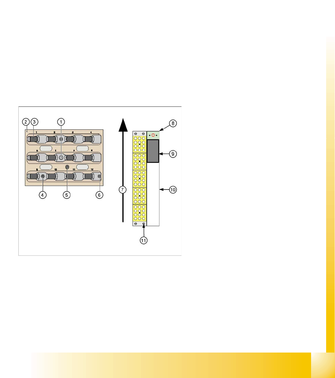
3.2.7.4 Nozzle changer for 12 segment C&P head
Optionally, a nozzle changer can be installed for each C&P head. This enables the nozzle configuration
to be changed quickly, thus allowing the Collect&Place head to be quickly adapted to the needs of the
placement process.
The nozzle changer consists of at least one and up to five magazines, each of which is equipped with
up to twelve nozzle garages. The magazines are seated on a common support and each magazine is
centered using two pins and is fixed in place with a spring hook.
Each garage can be configured with different nozzle types.
Legend:
1. Calibration fiducial
2. Locking Plate
3. Nozzle garage
4. Hole for centering pin, for exact positioning of
magazine
5. Hole for driver pin, for opening and closing of
magazine
6. Slit for centering pin, for exact positioning of
magazine
7. Transport direction
8. Nozzle reject device
9. Nozzle reject container
10. Tape duct
11. Fastening screws for nozzle changer (4x)
Overview
General Overview of Assemblies SIPLACE Vision
Student Guide SIPLACE D4 (FSE)
Overview EN 09/2006
60
3.2.8 SIPLACE Vision
The digital SIPLACE Vision solution is another step towards the satisfaction of customer demands for
greater speed, flexibility and robustness.
Advantages of the digital Vision system:
Robust and fast computing algorithms
Flexible measurement processes
Intuitive graphical user interface
Geometric description of components at the machine
State-of-the-art digital camera hardware
Homogenous illumination of camera field of vision and components
Each C&P head has its own digital component camera.
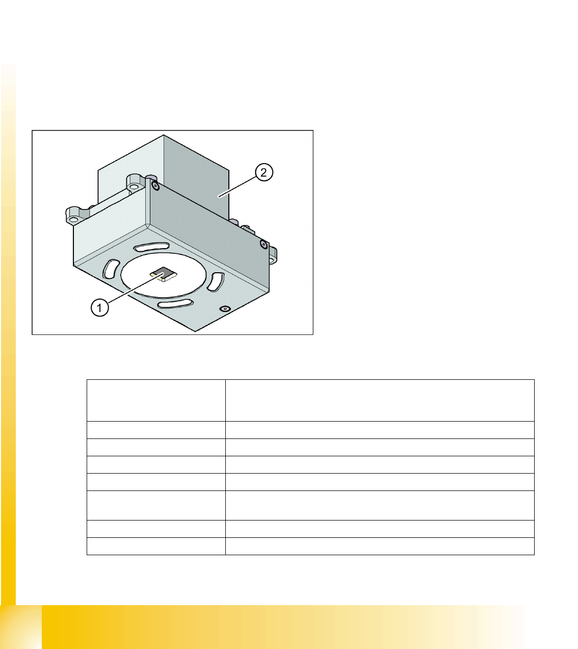
3.2.8.1 Digital PCB Camera (Type 34)
3.2.8.1.6 Technical data
Legend:
1. PCB camera optics and illumination
2. Camera amplifier
PCB fiducials Up to 3 (panels and cluster panels),
Up to 6 for the option "long board" (optional fiducials are issued by the
optimization process).
Local fiducials Up to 2 per PCB (can be of different types)
Library archive Up to 255 fiducial types per panel
Image processing Edge detection method (single feature) based on gray values
Method of illumination Front-lighting (3 levels, programable as required)
Recognition time per
Fiducial/poor fiducial
20 ms - 200 ms
Field of vision 5.78 x 5.78 mm2
Distance from the focus plane 28 mm

Overview
SIPLACE Vision General Overview of Assemblies
Student Guide SIPLACE D4 (FSE)
EN 09/2006 Overview
61
3.2.8.1.7 Fiducial Criteria
Determine 2 fiducials X/Y position, angle of twist, central PCB displacement
Determine 3 fiducials Additional: shearing, displacement separately in X and Y direction
Fiducial shapes Synthetic fiducials: circle , cross , square , rectangle , diamond , circular,
square and rectangular contours, doublecross
Pattern: any
Fiducial surface
Copper Without oxidation and soldering paste
Tin Warpage 1/10 of the structure width, with good contrast to surroundings
Dimensions of synthetic fiducials
Min. X/ Y size for circle and rectangle: 0.25 mm
Min. X/ Y size for square ring and rectangle frame: 0.3 mm
Min. X/ Y size for cross: 0.3 mm
Min. X/ Y size for doublecross: 0.5 mm
Min. X/ Y size for diamond: 0,35 mm
Min. frame width for square ring and rectangle frame: 0,1 mm
Min. bar width/bar spacing for cross, doublecross: 0,1 mm
Max. X/ Y size for all fiducial shapes: 3 mm
Max. bar width/bar spacing for cross, doublecross: 1,5 mm
Min. general tolerances: 2% of nominal
dimensions
Max. general tolerances: 20% of nominal
dimensions
Dimensions of templates
Min. size 0.5 mm
Max. size 3 mm
Fiducial surroundings Space is not needed around the fiducials, provided there are no other similar
fiducial structures in the search field.