YesAX V3.1.2 - Software User Manual.pdf - 第103页
General Inspecti on Methodolo gy 10 -9 The two boxes must overlap to allow the stitching operation to work. Both marking should have Decision algorithm set to Barcode. I n the Bar Code Parameters dialog, the Is half of a…
10-8 General Inspection Methodology
The Reposition Camera After Retry Failed checkbox, if checked, would shift the camera in a
pre-defined distance if the retry still fails. The camera will move to the place where the barcode
string can be seen so that the user can type the barcode in the corresponding field. The shifting
distance can be set in YesAX.ini file, under Barcode session. The names are “RePosDx” and
“RePosDy”, respectively. The unit is in micron.
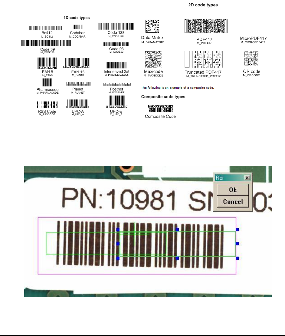
10.2.3.1 Barcode Types
Below are some examples of the supported code types.
10.2.3.2 Barcode Stitching
YesAX software has the ability to read barcodes larger than the field of view of the top camera.
The software stitches two images together before performing the barcode read operation. To
utilize the feature user should train two marking boxes each for half of the barcode.
General Inspection Methodology 10-9
The two boxes must overlap to allow the stitching operation to work. Both marking should have
Decision algorithm set to Barcode. In the Bar Code Parameters dialog, the Is half of a barcode
checkbox needs to be checked.
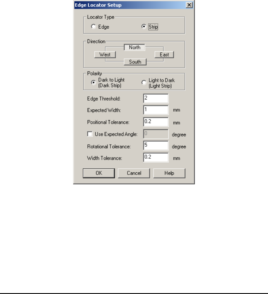
10.2.4 Edge Locator Parameters
Another decision algorithm for mark is Edge Locator. The edge locator locates edges’ position
and angle down to ¼ pixel resolution.
Available only when Edge Locator is selected as the decision algorithm menu item.
Select Edge Locator Params.. from the Mark pop-up menu to open the Edge Locator Setup
dialog.
The Locator Type group selects whether the Edge Locator looks for an edge or strip. A strip is
defined as a pair of edges of the opposite polarity.
The Direction parameter selects the direction for the edge or strip. The West and East directions
select vertical edges and the North and South director are for horizontal edges. The Direction
must be set before Polarity can be set. The search operation should always start from the outside
moving toward the center. For example if the direction is west, search operation goes from left to
right. If direction is East search operation goes from right to left.
The Polarity check box specifies the polarity. For an Edge locator the polarity could be set to
either from Dark to Light or from Light to Dark. For a Strip locator the polarity could be set to
either a Dark Strip or a Light Strip.
10-10 General Inspection Methodology
The Edge Threshold defines the minimum edges strength. Edge strength ranges from 0 to 100.
The Expected Width set the expected width of a strip.
The Positional, Rotational and Width Tolerances define the tolerance for the position, angle
and width.
The default angle is 0 degree. If user enables Use Expected Angle and set a number for the
desired angle, software will use this as default angle instead of 0 degree.
10.3 Lead Bank Inspection
Lead Bank inspection checks for leads of IC components as well as solder balls of BGA
components. The default algorithm for lead bank inspection of IC components is Blob analysis.
The default algorithm for lead bank inspection of BGA components is BGA Group (see 10.5.2
Lead Bank Inspection). The default algorithm for bond wire inspection of bond wire components
is Bond Wire Sweep analysis.
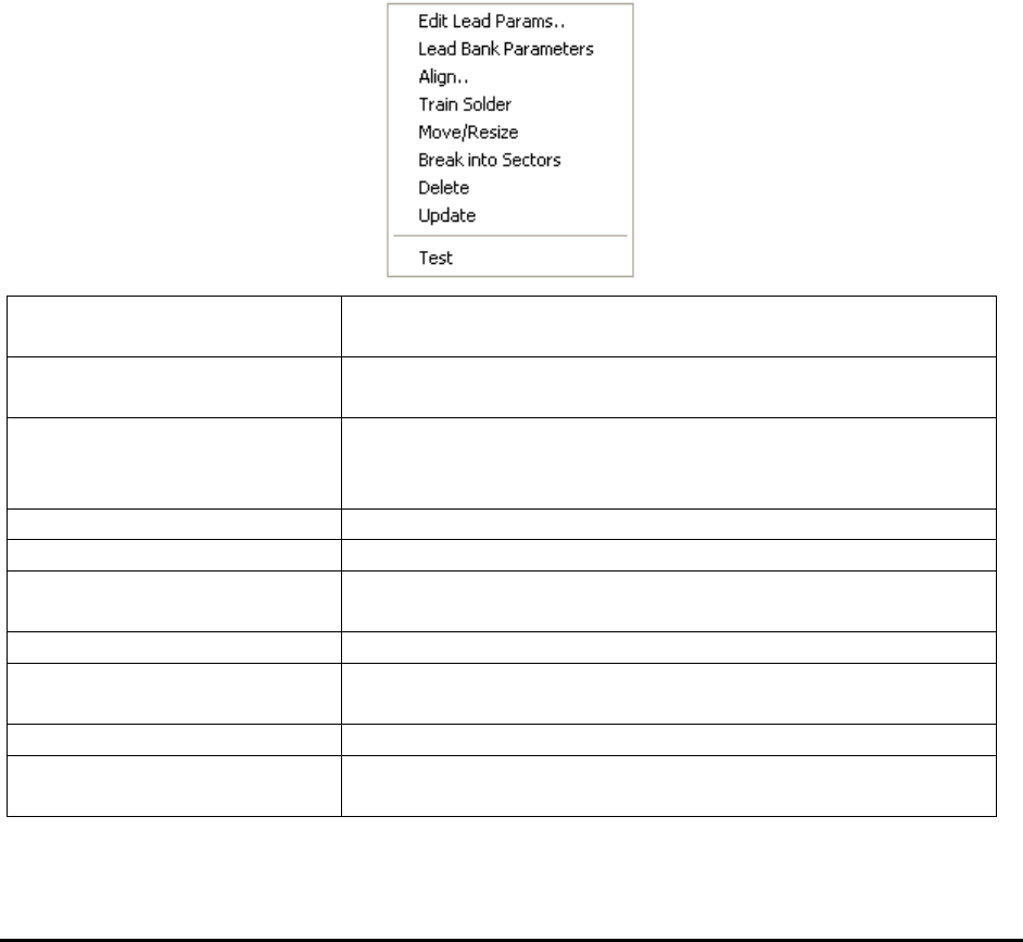
After a lead bank inspection box is created, display the Lead Bank pop-up menu by pressing the
right mouse button while pointing at the inspection box.
Edit Lead Params..
Launches the Lead Bank Parameters dialog. See 10.3.1 Edit
Lead Bank Parameters.
Lead Bank Parameters
Launches the Lead Blob Analysis Parameter dialog. See
10.3.2 Lead Blob Analysis Parameter
Align..
Launches the Lead Bank Alignment dialog to allow
alignment of the lead bank inspection box. See 10.3.3 Lead
Bank Alignment.
Train Solder
Trains the solder inspection within the lead bank.
Move/Resize
Moves or resizes the lead bank inspection box.
Break into Sectors
Breaks up a long lead bank into smaller sectors. See 10.3.4
Break Lead Bank into Sectors.
Delete
Deletes the inspection box.
Update
Uses the current lead bank as reference to update the
parameters of other lead banks. See 10.3.5 Update Lead
Test
Tests the lead bank inspection on the current image.
Bond Wire Params..
Launches the Bond Wire Sweep Parameters dialog. See
10.3.6 Bond Wire Params..