YesAX V3.1.2 - Software User Manual.pdf - 第82页
7- 12 3D Recipe Creatio n At the top of the dialog, the software suggests setting X-ray power level for BGA inspection. Move the mouse pointer to an area between the BGA balls and read the gray level at the status window…
3D Recipe Creation 7-11
You should not need to move very far from the initial position to locate this alignment box. If
you need to move more than 10 mm, the scale in the YPC file may be wrong. Also, the software
will not allow the user to continue if it detected the user make an adjustment more than 10 mm
for the bottom right alignment pin.
NOTE
Y2701 has to be a part located near the bottom right corner of the board, and pin 4
has to be located near bottom right corner of Y2701.
You should not need to move very far from the initial position to location this alignment box. If
you need to move more than 10 mm, the scale in the YPC file is wrong. Also, the software will
abort if it detects the user make an adjustment of more than 10 mm for the bottom right
alignment pin.
The last alignment pin is a top left pin. |This alignment pin should be very close to its initial
location. The software will abort the import process if the user makes an adjustment of more than
10 mm for this third alignment.
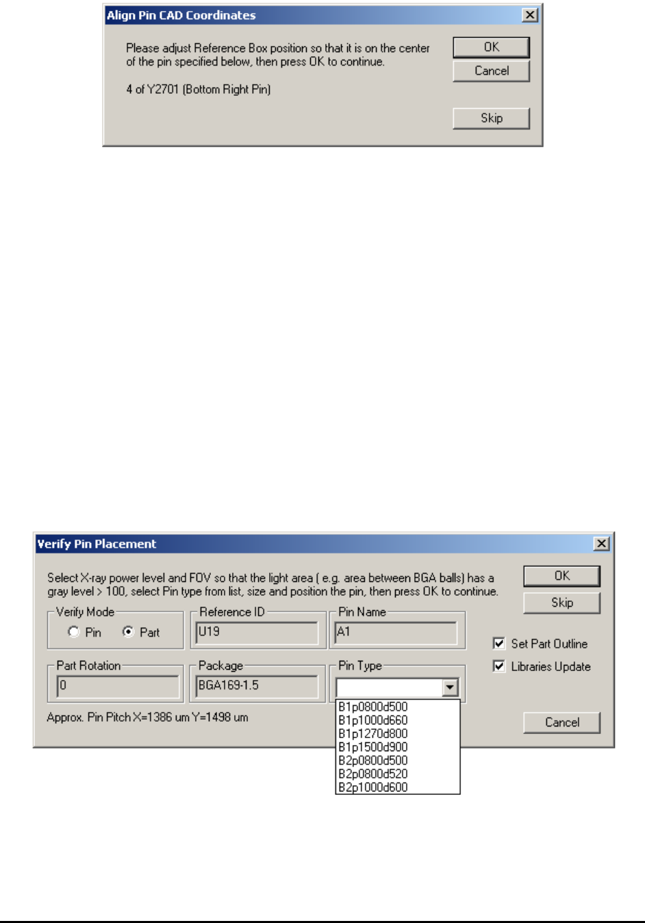
After the alignment, the import process begins. The import process follows the sequence in the
YPC file, skipping over parts that are not in the part list. The Verify Pin Placement dialog
displays for the first pin (or solder joint) of each part to verify (or adjust) the pin’s XY positions.

7-12 3D Recipe Creation
At the top of the dialog, the software suggests setting X-ray power level for BGA inspection.
Move the mouse pointer to an area between the BGA balls and read the gray level at the status
window at the bottom right corner of the screen. The dialog also approximates the pitch of the
BGA. The information can help when selecting Pin Type from a standard pin library (refer to
13.6 Pin Library). Selecting Pin Type is optional and can be left blank if preferred.
Select either Pin Mode or Part Mode. Pin Mode will prompt the user to. The Verify Mode
section of the dialog gives the user the opportunity to re-size and re-position the pin.
By selecting Pin Mode, the user is prompted to verify every pin (this could take some time on a
1000+ pin BGA). When selecting Part Mode (probably most common), the user is prompted to
verify the first pin of every part. Sizing the first pin will set the size for all pins on the part.
Selecting the Set Part Outline checkbox instructs the software to set the part’s size and center
position (purple box) based on the positions of its pins. It should be checked for BGA and
Through-hole connector packages, and unchecked for other packages. It is usually easier to align
the Pin CAD data to greater accuracy than to align the part centroid data of the YCD file. This
feature eliminates the need to spend time adjusting part size during the YCD file import for BGA
and through-hole connector packages.
Selecting the Libraries Update checkbox instructs the software to update the parts, with the
same package, with newly acquired part information. Enable this for all the SMT parts. The only
time you may want it uncheck is for importing pin CAD for PTH parts (e.g. connectors) where
the YCD file contains a pin 1 XY position rather than a centroid XY position.
The Pin CAD import process creates solder inspection boxes for each pin (solder joint) with
Neutral direction and default algorithm (Histogram). User will need to switch them into the
correct algorithm for the inspection. The new inspection algorithm “BGA Pin Inspection” (a
solder algorithm) is designed to replace both BGA group ( a lead algorithm) and BGA Analysis
(a solder algorithm). The BGA Pin Inspection algorithm is currently the most likely algorithm
being used in conjunction with the Pin CAD import feature.
Train Part without CAD data 8-1
8 - Train Part without CAD data
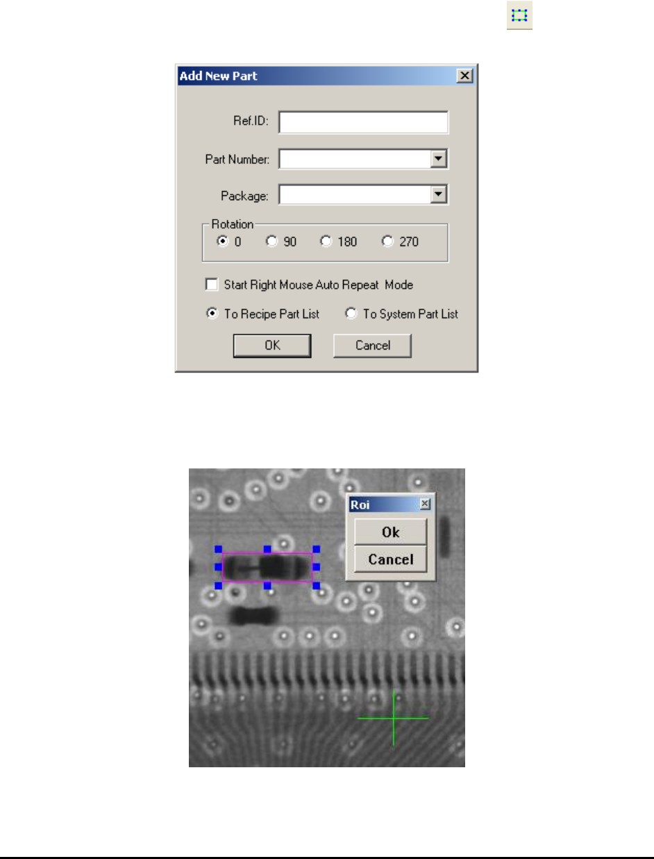
It is possible to train parts without CAD data. To add parts this way first move the camera so that
the part to be trained is in the field of view, then press the Add Part button on the toolbar.
The Add New Part dialog displays.
Enter the Reference ID of the part to be trained, and select from the Part Number list if the part
is in the part library. If the part is not in the part library, but its package is in the package library,
select the corresponding package of the part. Specify part rotation by selecting from one of the
radio buttons in the Rotation group.
After pressing OK on the Add New Part dialog, specify the part’s exact location by overlaying a
region of interest box on the part.