YesAX V3.1.2 - Software User Manual.pdf - 第33页
Unpacking and Installation 3-3 3.7 Connect th e Machine The X2/X3 AXI System requires 120V sing le phase AC power. It draws about 7 amps of continuous current. Because of its low power consumption, it can be plugg ed int…
3-2 Unpacking and Installation
3.5 Install the LCD Monitor
To prevent damage during shipment, the LCD monitor is removed from the machine and shipped
in its own protective package. When the X2/X3 AXI System leaves the factory, the monitor arm
assembly is attached to the left side of the machine. However, the monitor arm assembly can be
attached to either the left or the right side of the machine. During installation you would decide
which side would be the most appropriate for attaching the monitor arm assembly.
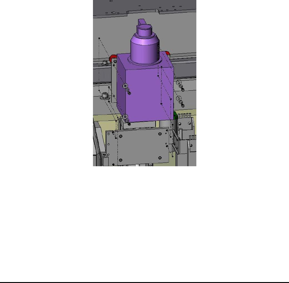
3.6 Install the X-ray Tube
To prevent damage during shipment, the X-ray tube is removed from the machine and shipped in
its own protective package. The X-ray tube needs to be installed into the machine during
installation. The X-ray tube is held by 4 (1 ½” length ¼ 20 thread) screws. A (3/16”) T-handle
Allen wrench is shipped with the system for those screws.
There is a protective stainless steel cover covering the X-ray emitting port. It needs to be
removed before operation.
Unpacking and Installation 3-3
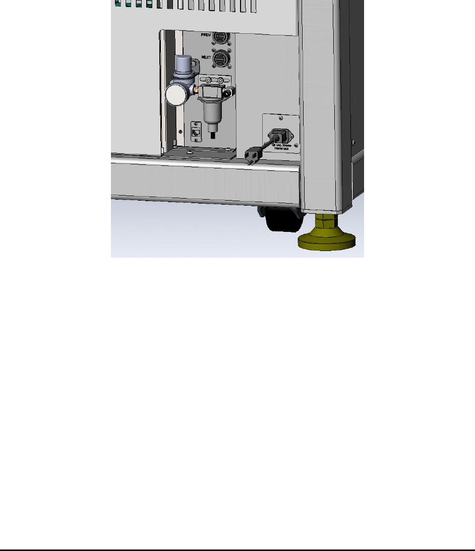
3.7 Connect the Machine
The X2/X3 AXI System requires 120V single phase AC power. It draws about 7 amps of
continuous current. Because of its low power consumption, it can be plugged into any common
electrical outlet. The system also needs compressed air to operate its pneumatics with 80 psi or
higher air pressure required. Air inlet requires ¼ inch OD tubing.
Although not necessary, it is a good idea to connect Ethernet to the machine’s computer. There is
an extension that extends the network socket from the back of the computer to the left side of the
machine. Plug the network cable into that extension.
3.8 Power On
The AC power first enters the machine via a circuit breaker which is mounted inside the base
cabinet. This circuit breaker is left in the ON position when the machine leaves the factory. Open
the lower back panel to access the main circuit breaker. After the circuit breaker the power then
reaches the emergency stop (E-Stop) switch and the power key, switch both in front of the
machine. To power-on, pull the E-Stop to its out position. The keys for the front power key
switch are tie-wrapped onto the red shipping bracket during shipment. Remove and insert the key
into the key switch and turn it clockwise to unlock the power.
The last step in the power-on process is to turn on the computer. Open the lower front cabinet
doors to gain access to the computer. The user may also need to turn on power to the LCD
monitor. The computer and the monitor get their power from a Un-Interruptible Power Supply
(UPS). There are times when the UPS needs to be reset. There is a red momentary push button
on the UPS, pushing it will reset the UPS. Open the lower back panel to access the reset button
on the UPS. In fact the reset button is located below the main circuit break mentioned earlier.
3-4 Unpacking and Installation
3.9 Verify Calibration
After the computer boots up, double click on the YesAX software icon on the desktop to
launch the YesAX control software. The software will prompt the user to log in. Use the
following User Name and Password:
User Name: user
Password: user
This is the default account with all the privileges. Different accounts can be setup to
accommodate specific needs. Refer to Section 20 - User Administration for details.
As an optional final step, machine calibration can be verified using the “Machine Builder” mode .
The first step is to “Home the Conveyor”. Refer to Section 9 - SMEMA Conveyor Setup for
details. Afterward, run the Self Test to verify all the machine calibrations. Refer to Section 25 -
Calibration and Verification for details.
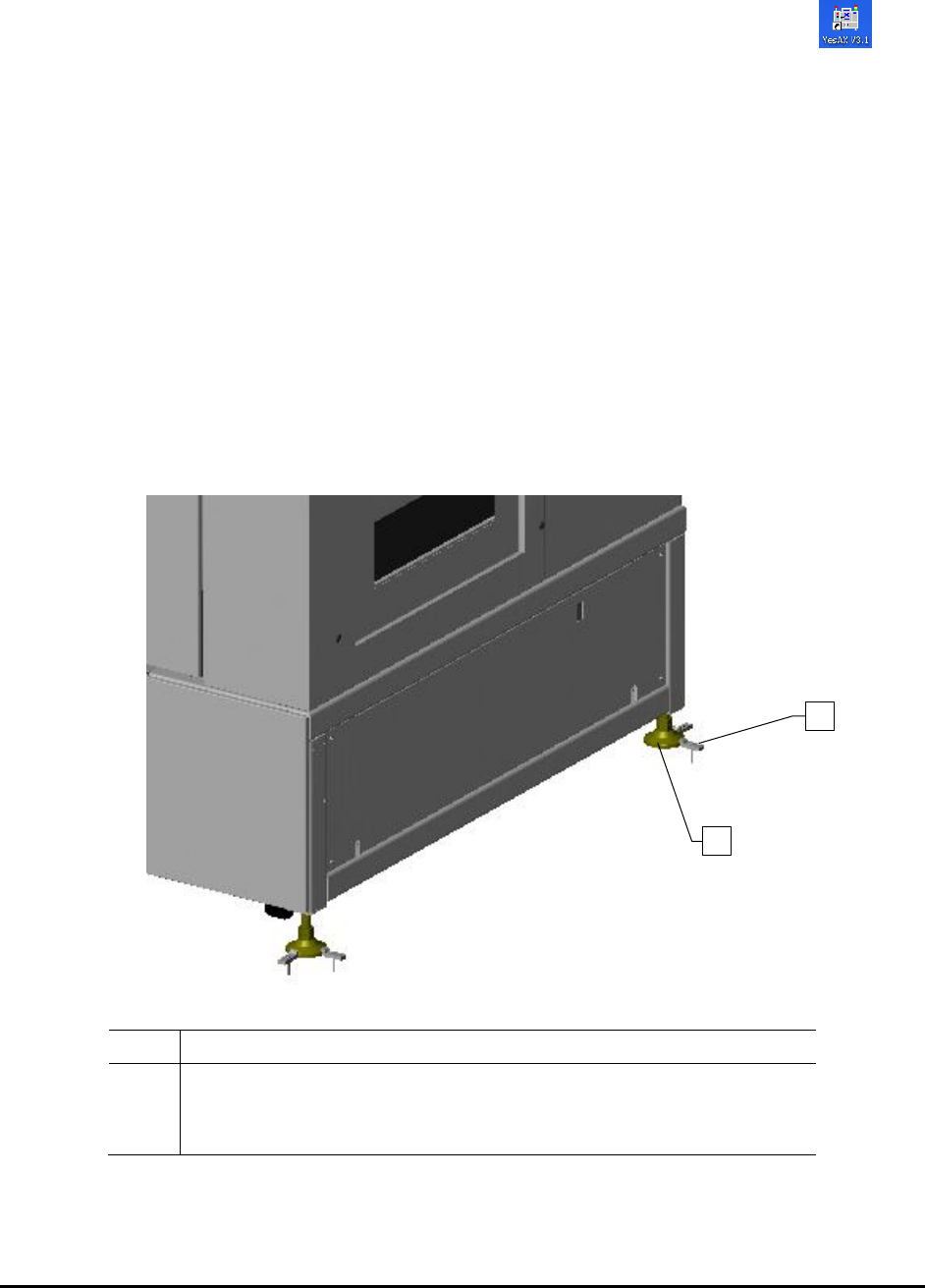
3.10 Seismic Safety
The AXI system is structurally designed to withstand seismic activity in accordance with industry
standards. Seismic brackets (Figure 3-1) should be installed on each footpad to anchor the system to the
floor per facility requirements.
Item
Description
1
Seismic Brackets (Two per corner)
Nordson YESTECH recommends JW WINCO Part#A71027
2
Leveling Pad
Figure 3-1 Seismic Brackets
1
2