YesAX V3.1.2 - Software User Manual.pdf - 第72页
7-2 3D Recipe Creatio n 7.2 CAD Con version Utilities 7.2.1 Convert5DX Utilit y The Convert5DX Utility is a file conversion utility that extracts board information from NDF files (Neutral Data Files and generates the nec…

3D Recipe Creation 7-1
7 - 3D Recipe Creation
7.1 Basic Concepts and Terminology
3D inspection introduces several new concepts and terminology. It is important to have some
basic understanding of them before trying to create 3D inspection recipes.
1. Tomosynthesis
Tomosynthesis is a technique that digitally combines oblique angle images to compose cross
section slices of the object being imaged. In the X3 system, tomosysnthesis is used to
combine 4 to 72 oblique angle images to compose the cross section slice of the circuit board
being inspected.
2. Site and Future Site
A site is an XY location on the board where 3D inspection takes place. A normal site is
indicated as a white circle in the map view. A normal site contains the angle images taken at
the site. These angle images can be combined to form horizontal X-ray “slices” of the area. A
future site is a site without the angle images. It is indicated in the map view as a magenta
cross. Future sites can be converted into normal sites by selecting Re-Capture all Sites in
the 3D Control pop-up menu, or the Capture Image Set button in the 3D Future Site dialog.
3. Slice and Slice Number
A slice is a composed image that represents a cross section of the site area in horizontal
orientation. There are two fields of view on the X3 that produce slices of two thicknesses,
25.8 um and 12.9 um. In YesAx slices are given numbers to represent their relative height
position. The top surface of the board has slice number 0, the number increases with height.
Slices for the bottom side parts have negative numbers.
4. Pitch and Roll
By default, the 3D slice obtained from tomosynthesis is exactly horizontal and parallel to the
conveyor rail. In an ideal case that is parallel to the board surface. However, in a real
production environment, the board surface is not always flat. To achieve a precise inspection,
the X3 system does additional computations to produce a slice that is parallel to the board
surface even when the board surface is not flat. The software utilizes the height data obtained
from the laser height measurement and applies a “pitch” and a “roll” factor in the
computation of the slice.
5. Surface Height Referencing
For precise 3D inspections, height referencing is extremely important. The X3 machine uses
2 very different techniques to precisely locate both the top and the bottom board surfaces.
The laser height gauge profiles the top board surface. Although the laser gauge has a short
term repeatability of a few microns, in a production environment with temperate variation
throughout the day, the practical accuracy for the laser gauge is around 30 microns, which is
not good enough for some of the more critical inspection requirements. Moreover, laser
gauges cannot be used to profile the bottom surface. Board thickness variation is quite
common for post reflow boards. In the X3, lasers are used to profile the top surface height
and to provide data for the pitch and roll calculation. Then a software technique called “Auto
Calculate” is used to precisely locate both the top and the bottom board surfaces.
7-2 3D Recipe Creation
7.2 CAD Conversion Utilities
7.2.1 Convert5DX Utility
The Convert5DX Utility is a file conversion utility that extracts board information from NDF
files (Neutral Data Files and generates the necessary YCD and YPC files for YesAX software
recipe generation.
The NDF files
As a necessary step in creating inspection programs for Agilent 5DX machines, you are asked to
create a number of NDF files (Neutral Data File) which describe the board in great detail. The
NDF files are text files with different NDF files describing different aspects of the board. The
Board.ndf files contain part information useful for generating the YCD files and the
LandPat.ndf file contains the Pin information which is useful for generating the YPC file.
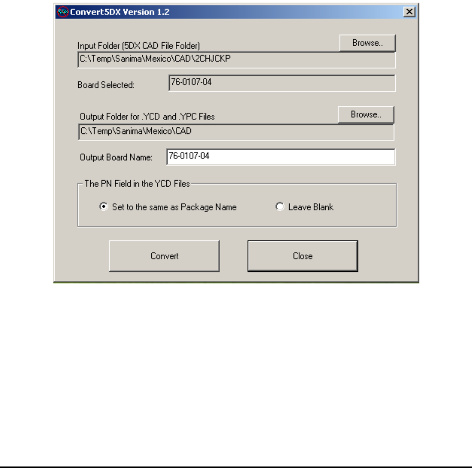
Here is the main user interface of the Convert5DX program:
Select the input folder where the directory structure for the 5DX NDF files is located.
Select the output folder where all the YCD and YPC files will be created.
After the folders are selected, press the “Convert” button to start the conversion process.
3D Recipe Creation 7-3
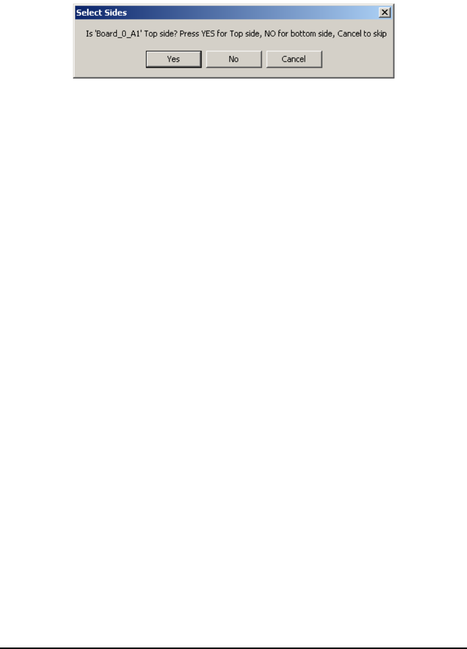
The Select Sides dialog will display twice to determine the sides.
The first prompt asks if the board is a top side and the second prompt asks if the board is a
bottom side. For a top side board, the correct responses would be “Yes” on the first prompt and
“No” on the other prompt.
5DX names the board side different from X3. Using X3 convention you may say 5DX usually
inspects board up-side-down. The term “Secondary Side” in 5DX usually refers to the top side
for X3. The only way to be certain is to try it. Since the conversion process takes no more than a
few minutes, trying out the combination will take no more than 10 minutes. The side convention
for each customer site is usually consistent, so once you figure it out, the next board should be
the same.
The conversion process generates a total of 4 YCD files and 2 YPC files.
BoardName_Full_T.YCD and BoardName_Full_B.YCD are YCD files for top and bottom
side of the board with all the parts in them.
BoardName_BGA_T.YCD and BoardName_BGA_B.YCD are YCD files for top and bottom
side with only BGA parts plus the parts needed for CAD alignment (parts near the corners of the
boards). Copy and paste additional parts from the BoardName_Full_x.YCD file into the
BoardName_BGA_x.YCD if more parts are needed to be imported.
For best utilization of the X3’s 3D inspection capability, Nordson YESTECH recommends using
it only to inspect BGA and Through Connectors. Other parts are more efficiently inspected by
AOI machines.
The two YPC files are BoardName.YPC and BoardName_Sorted.YPC. These two files may
be identical for a lot of the boards where the entries for pin in the 5DX LANDPAT.NDF file are
sorted by pin name. Always use the sorted version for pin CAD import on the YesAX software.