YesAX V3.1.2 - Software User Manual.pdf - 第148页
11 -4 3D X-Ray Inspection Methodology 2D X-ray image cannot determine barrel condition 3D Slice image showing solder not reaching the bottom surface of the circuit board. 11.2 User Interface for 3D Insp ection The 3D Con…
3D X-Ray Inspection Methodology 11-3
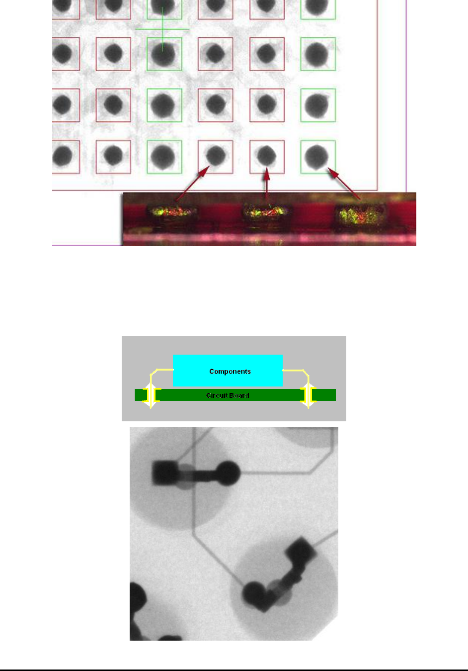
11.1.3 Detect Barrel Fill Condition for PTH
For plated through hole (PTH) circuit boards, component leads (pins) go from the component
side pass through the board and be soldered on the solder side of the board. For high reliability
circuit the solder should be wetted into the hole and completely fill the barrel. 3D X-ray imaging
can be used to verify the solder condition inside the barrel of the PTH circuit board.
11-4 3D X-Ray Inspection Methodology
2D X-ray image cannot determine barrel condition
3D Slice image showing solder not reaching the bottom surface of the circuit board.
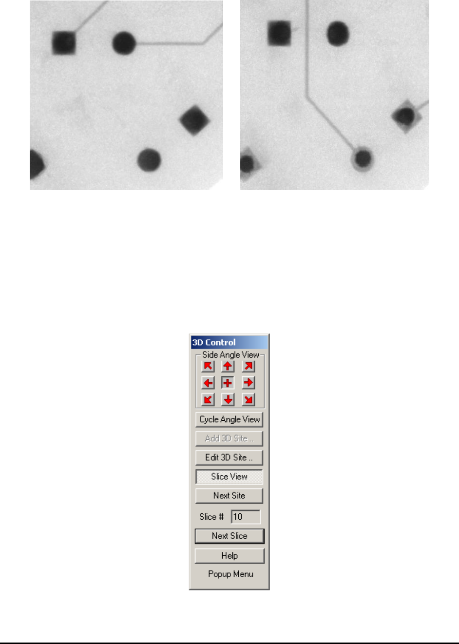
11.2 User Interface for 3D Inspection
The 3D Control dialog (shown below) will always be on top of the screen. It can also be moved
around within the YesAX window and software will remember the position after each move, just
like the X-ray control window.
Side Angle View buttons allow the user to step through the 8 side angled views at 0, 45, 90, 135,
180, 225, 270 and 315 degrees. Center “+” image represents the regular 2D (top-down) view.
When navigating through sample board, it is advisable to use regular 2D view only.
Cycle Angle View button will cycle between all 8 angle views and the 2D view.

3D X-Ray Inspection Methodology 11-5
Add 3D Site button, when clicked, will capture 9 total images from different angles at the
current site, and then launch the Add 3D Site dialog window. Before clicking this button, please
make sure to use X-Ray camera, , by clicking on the X-Ray camera button and ensure that
you are in 2D mode by checking that the “Slice View” button is not depressed and that the “+”
button in the dialog is pressed. Two FOVs may be used for 3D mode, either 1” or 0.5”. Please
check that one of these FOVs is selected before adding a 3D site. Once an FOV is selected, an X-
ray power level must be selected. The power level setting affects the brightness of the image.
Select a power setting by choosing a brightness that is best suited for defect detection.
Edit 3D Site button when clicked will launch the Edit 3D Site dialog. The button will only be
clickable when there is a 3D site available and the site is right at current position.
Slice View button when clicked will toggle between 3D slice view mode and normal 2D view
mode. When the button’s been pressed down, system is in 3D slice view mode. Otherwise the
system is in 2D view mode. Each time after this button’s been pressed, status of the other buttons
in 3D control window will also be updated, whether be disabled or not. When in normal 2D view
mode, if there is at least one 3D site already defined in current FOV, click the Slice View button
will also move stage to the nearest 3D site position.
Next Site button when clicked will step through 3D sites one at a time. This button will allow
user navigate through different 3D sites easily.
Slice # field indicates the slice number, within current 3D site.
Next Slice button when clicked will step through slices within current 3D site, one at a time.
This button will allow user navigate through different slices with same site easily.
11.3 Add 3D Site
Before adding a 3D site, it is important to make sure to select X-Ray camera view and the
regular 2D view. It is also a good idea to pick the right FOV (either 1” or 0.5” FOV for X3) and
right X-ray power level setting for the device being inspected.
Once everything is ready, one click of the Add 3D Site button will prompt system to capture one
set of side angle images at current stage position automatically. After that the Add 3D Site dialog
will be launched. Slice at level 0 will be constructed and shown on screen. For 3D programming
the top side of the board is always set to at slice level 0 and should never be changed.