YesAX V3.1.2 - Software User Manual.pdf - 第68页
6- 10 Recipe Creation Step by Step for 2D Re cipes 6.5 User Practice You can practice the recipe creation process by using the demo ImageSets and demo CAD data files. The sample CAD data files can be found in folder: C: …
Recipe Creation Step by Step for 2D Recipes 6-9
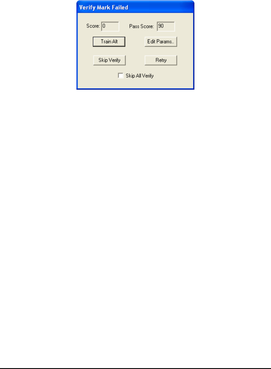
The part marking verification inspects the part’s marking and if it passes, the part is placed in the
inspection list of the recipe. If the inspection fails the Verify Mark Failed dialog displays.
Train Alt Button
Use to train alternate templates
Edit Params… Button
Use to launch the Part Parameter dialog for the user to change the marking parameters, such
as lowering the pass score.
Skip Verify Button
Use to skip the verification for this part only.
Retry Button
Use to return to the Verify Part Marking dialog.
Skip All Verify Checkbox
Select to turn off part verification for all parts. This checkbox is also on the Verify Part
Marking dialog or Train New Part dialog. When marking verification is turned off, the part is
added to the inspection list without being verified.
The verification process is commonly used as “First Article Inspection” for the assembly. This
way the user can create an inspection recipe and do the first article inspection at the same time.
This process is complete when all the parts imported are verified.
The part import process can be aborted at any time by pressing the Cancel button on the Verify
Part Marking dialog, Train New Part dialog or the Stop button on the Setup CAD Parameters
dialog. The parts that are imported up to this point will remain in the part list. To resume the
import process, simply select CAD Data, Import CAD from the file menu. Since the part
information in the CAD file merges with the part information in the recipe, there is no danger of
importing the same part twice.
6.4 Step4: Fine-Tune the Inspection Parameters
After CAD import, run 3 to 5 boards to fine tune the inspection parameters. Nordson YESTECH
also recommends running a bare board test to make sure the inspection thresholds are not set too
loose.
6-10 Recipe Creation Step by Step for 2D Recipes
6.5 User Practice
You can practice the recipe creation process by using the demo ImageSets and demo CAD data
files. The sample CAD data files can be found in folder:
C:\AOI_Data\CAD_Data\Demo
The CAD data belongs to two boards: Demo_X2 and Demo X3. Demo_X2 is a single sided
board with 2 sets of CAD data files:
Demo_X2_2.ycd - contains all the information (required and optional) to create the recipe.
Demo_X2.ycd - similar to Demo_X2_2.ycd with the exception that the package names do
not match the package names in the standard package library.
Demo_X3_3 is a double sided board with 2 sets of CAD data files:
Demo_X3_3_Top.ycd - contains all the information of components on top side to create the
recipe.
Demo_X3_3_Bot.ycd – contains all the information of components on bottom side to create
the recipe.
Practice creating recipes using each of the files to see how the additional (optional) information
in the CAD data aid in the recipe creation process.
Practice creating recipes using Demo_X2.ycd to understand the usage of the package name map
feature.
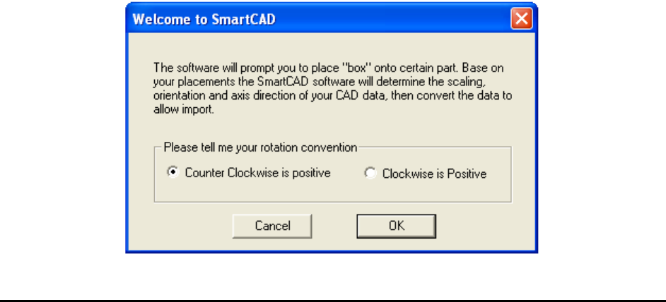
6.6 SmartCAD
During normal CAD import the software requires you to correctly state the CAD data’s axis
orientation, scale, and rotation information in the header section of the YCD file. The SmartCAD
feature helps you to determine such information by asking the user to locate several parts (3 to 6)
on the board. Based on user’s input the software calculates the required information.
To use the SmartCAD feature, set the scale factor line to “Auto” in the header section of the
YCD file.
ScaleFactor=Auto
In the beginning of the CAD import process the Welcome to SmartCAD dialog displays
indicating that the software is utilizing the SmartCAD feature.

Recipe Creation Step by Step for 2D Recipes 6-11
You can create a perfectly functional AXI recipe using SmartCAD, even when the PCB is placed
90 or 180 degrees from the intended orientation.
Although SmartCAD is very efficient in determining needed information from “mystery” CAD
data, it should be used with caution. CAD data is the basis of the PCB assembly process but
SmartCAD creates usable AXI recipes without knowing much about the CAD data. This can
lead to bad consequences in the future when more advanced features are used, such as the central
library and standard package library.
Sharing part information across inspection recipes requires a consistent application of part
rotation information.