YesAX V3.1.2 - Software User Manual.pdf - 第80页
7- 10 3D Recipe Creatio n NOTE there is only one YPC file for both sides (top and bottom side) of the board’s solder joints. For double sided boards (i.e. BGA component mounted on both sides of the board), import the s…

3D Recipe Creation 7-9
7.5 Pin CAD
The Pin CAD feature is added to YesAX version 3.03 to allow inspection recipe creation by
utilizing the information from CAD data for the locations of BGA balls or through-hole (PTH)
pins. This “Pin CAD” import feature can greatly reduce programming time for complex BGAs
and through-hole connectors.
The Pin CAD Feature
The Part CAD and Pin CAD features
Most application engineers are quite familiar with the part CAD feature (*.YCD) of the YesAX
software. This feature was inherited from the AOI software (YesVision) that imports the
reference designators (Ref.ID), part number, centroid position, rotation and package of every part
on the circuit board. The Pin CAD feature (*.YPC) imports the centroid XY position of each
solder joint. The Pin CAD feature DOES NOT replace the Part CAD feature. In fact, they work
together. You cannot import any YPC files without first creating the part list by importing the
YCD file.
The YPC files are text files with formats similar to that of the YCD files. There is a header
section where you specify scale, axes inversion, board rotation, etc., then follows by a list of all
the pin locations. The pins’ XY locations are given in board coordinates. That means they have
the same origin (0,0) as the part centroid locations in the YCD files. Here is a fragment of an
YPC file:
.YTX_PIN_CAD_DATA
[Header]
Version= 1
ScaleFactor= 25400
InvertX_T= 0
InvertY_T= 0
InvertX_B= 1
InvertY_B= 0
BoardRotation= 0
.START_PIN_LIST
Line Part Pin X Y Type Comments
1 RX_1 1 1.2015 5.2007 ----
2 RX_1 2 1.2225 5.2007 ----
3 FX 1 0.252 5.7271 ----
4 RN4 A1 5.3597 5.3229 ----
5 RN4 A2 5.3991 5.3229 ----
6 RN4 A3 5.4385 5.3229 ----
7 RN4 A4 5.4778 5.3229 ----
8 RN4 A5 5.5172 5.3229 ----
9 RN4 A6 5.5566 5.3229 ----
10 RN4 A7 5.5959 5.3229 ----
11 RN4 A8 5.6353 5.3229 ----
12 RN4 A9 5.6747 5.3229 ----
13 RN4 A10 5.7141 5.3229 ----
14 RN4 A11 5.7534 5.3229 ----
15 RN4 A12 5.7928 5.3229 ----
16 RN4 A13 5.8322 5.3229 ----
17 RN4 A14 5.8715 5.3229 ----
18 RN4 A15 5.9109 5.3229 ----
.END_PIN_LIST
7-10 3D Recipe Creation
NOTE
there is only one YPC file for both sides (top and bottom side) of the board’s
solder joints. For double sided boards (i.e. BGA component mounted on both
sides of the board), import the same YPC file twice: one for the top side and the
other for the bottom side. Although a YPC file contains information for all the
solder joints on both sides of the board, during the import process only the parts
that are in the part list of the selected side will be imported.
Recipe Creation Process Outline
The recipe creation process is started by selecting “New Recipe or Side” from the File menu.
The Create New Inspection Recipe dialog displays. Define board size and train the alignment
marks. After that, capture an image set and create a map view background image. The next step
would be importing of the YCD file (or files if double sided board.). After the import of the YCD
files, the Pin CAD import process will begin. In the next section we will describe the Pin CAD
import process in detail.
It is assumed that users have a good understanding of the other steps of the recipe creation
process for the YesAX.
Pin CAD Import Process
The Pin CAD import process begins by selecting which side of the board (top or bottom) to
import. This is done by pressing one of the show part buttons. For example, to
import the top side part pins, the “Show Top Part” button needs to be selected. After board side
selection, open the YPC file by selecting File>CAD Data>Import Pin CAD
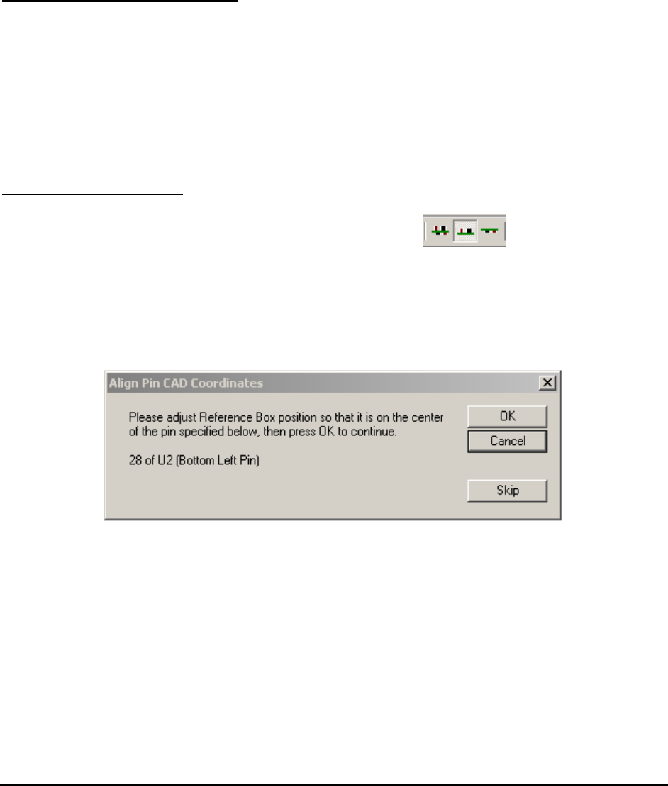
Similar to the YCD import process, in the YPC import process the user is prompted for the
location of 3 pins (bottom left, bottom right and top left) to align the coordinate system. The first
prompt dialog may look like this:
In this case, place the alignment box on top of pin 28 of U2.
NOTE
Be careful when placing the alignment box. The part U2 has to be located near the
bottom left corner of the board. If not, the “Board Rotation” entry in the header
section of the YPC file may be wrong. In addition, pin 28 has to be located at the
bottom left corner of U2. If not, the “Rotation Offset” entry of the YCD file may
be wrong. If either case happens cancel the import process, edit the YPC or YCD
file to fix the problem, and then re-start the import process again.
The second prompt for the pin CAD alignment may look like this:
3D Recipe Creation 7-11
You should not need to move very far from the initial position to locate this alignment box. If
you need to move more than 10 mm, the scale in the YPC file may be wrong. Also, the software
will not allow the user to continue if it detected the user make an adjustment more than 10 mm
for the bottom right alignment pin.
NOTE
Y2701 has to be a part located near the bottom right corner of the board, and pin 4
has to be located near bottom right corner of Y2701.
You should not need to move very far from the initial position to location this alignment box. If
you need to move more than 10 mm, the scale in the YPC file is wrong. Also, the software will
abort if it detects the user make an adjustment of more than 10 mm for the bottom right
alignment pin.
The last alignment pin is a top left pin. |This alignment pin should be very close to its initial
location. The software will abort the import process if the user makes an adjustment of more than
10 mm for this third alignment.
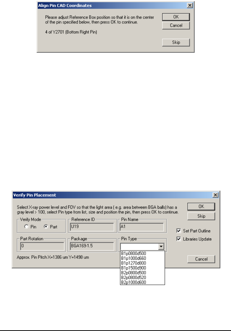
After the alignment, the import process begins. The import process follows the sequence in the
YPC file, skipping over parts that are not in the part list. The Verify Pin Placement dialog
displays for the first pin (or solder joint) of each part to verify (or adjust) the pin’s XY positions.