YesAX V3.1.2 - Software User Manual.pdf - 第92页
9-4 SMEMA Convey or S etup The Backout Time-out sets the time for the board to back-out from the stops. In normal operation, for left to right or right to left feed mode, the sy stem will allow the next board to enter th…
SMEMA Conveyor Setup 9-3
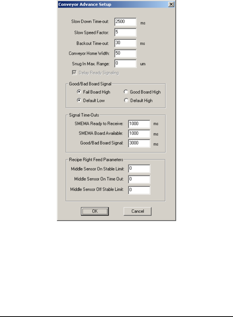
Press the Advance Setup button on the Conveyor Setup dialog to launch the Conveyor Advance
Setup dialog.
As the conveyor feeds a board and it reaches the middle sensor it slows down, and then slowly
creeps toward the hard stop.
The Slow Down Time-out is the time from the moment the middle sensor is triggered to the
time inspection begins. It is the time the board moves in slow speed mode.
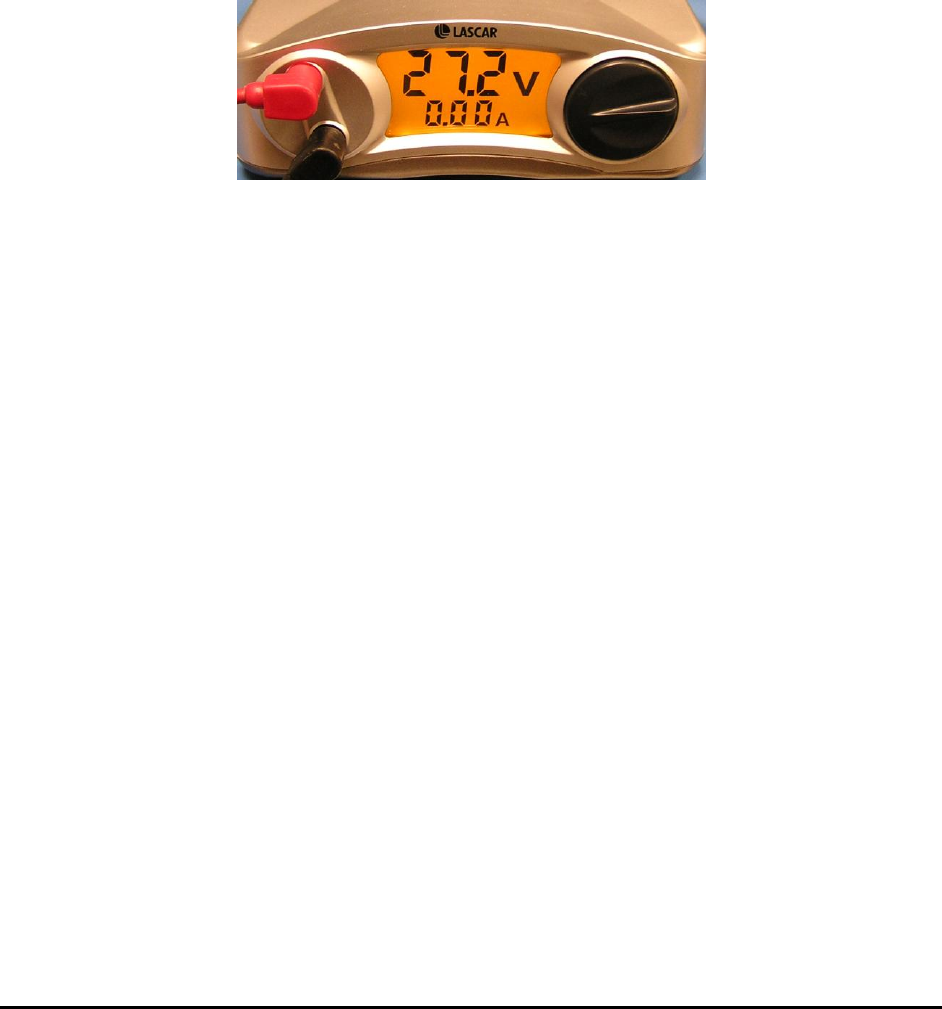
The Slow Speed Factor sets the speed of the slow speed mode. The slow speed is always a
fraction of the overall speed. The overall feed speed is controlled by adjusting the power supply
voltage of the conveyor feed motor (shown below). In left to right feed mode, to feed board from
inspection position to the right requires retracting the hard stops. In order to retract the hard stops
freely, the board needs to be backed out from it first.
9-4 SMEMA Conveyor Setup
The Backout Time-out sets the time for the board to back-out from the stops. In normal
operation, for left to right or right to left feed mode, the system will allow the next board to enter
the machine while the current board is exiting the machine which increases throughput.
Concurrent feeding can be disabled by checking the Delay Ready Signaling checkbox.
The Conveyor Home Width field defines the conveyor home width. Sometimes the conveyor
width could be a bit bigger than the actual board width. This may cause board position shift
during conveyor movement.
To prevent this situation from happening, set up a Snug In Max. Range. Once the board is
loaded the conveyor will keep snug in with the amount in the Snug In Max. Range field. This
will help secure the position of the board. The common values for this parameter could be set to
between 0 and 300 um.
In addition to the standard SMEMA, X2/X3 AXI systems also provide a signal called the
Good/Bad Board Signal that indicates the inspection status. It can be used to signal the
downstream equipment. The signal comes out from U8 pin 10 and is isolated by solid state relay
(SSR) U18 on the I/O board, then emerges as OUT6+ and OUT6- lines and connects to screw
terminal ST3’s pin 5 and pin 6. There are two 12-pin screw terminals on the I/O board with ST3
on the right. This signal’s characteristic can be configured using the Good/Bad Board Signal
section of the Conveyor Advance Setup dialog.
In the last section on the dialog, configure signal timings for the SMEMA signals and the
Good/Bad Board signal.
The Signal Time-Outs section configures signal timings for the SMEMA signals and the
Good/Bad Board signal.
The last section of the dialog defines three middle sensor related parameters. All three apply to
conveyor right feed mode only. How the machine see the boards can be controlled by adjusting
these parameters. These are per recipe settings and may need to be set differently to handle
different sizes of the board.
During right feed mode the board comes in from the right side and moves towards left to trigger
the middle sensor (Sensor On). Once the board passes the middle sensor (Sensor Off), the board
hard stop is down and the conveyor belt motor reverses direction. After “Slow Down Time-out”
board clamps and the inspection begins.
During right feed there may have several possible problem scenarios:
1. Big holes or cut-outs on the board which cause the middle sensor to go off before
the board passes through completely.
2. The middle sensor flickers off momentarily after it first sees the board.

SMEMA Conveyor Setup 9-5
3. A delay from the command issued to the pneumatic controls before the action
actually takes place. This may cause problems such as motor reversing before the
hard stop is down, which could cause board jam under the hard stop.
The Middle Sensor On Stable Limit and Middle Sensor On Time Out give user more control
over the middle sensor operations. They redefine the definition of On and Off. Normally the
software checks the sensor every 100 ms while the firmware checks the sensor continuously.
When Stable Limit is set to 0 as default, the middle sensor only has to report “On” once before it
is considered On by the software. If Stable Limit is set to 1, it will have to report On twice,
which means the middle sensor will remain on for 100 ms during that time. If Stable Limit is set
to 10, the middle sensor will need to see the board for one whole second (1000 ms, which is
highly unlikely in real situations) before it is considered as On by software. Therefore, the longer
in Y direction the board is, the bigger the Middle Sensor On Stable Limit will be. In case the
middle sensor misses the board, the left sensor will see the board and reverse the conveyor belt to
prevent boards from dropping.