YesAX V3.1.2 - Software User Manual.pdf - 第211页
SPC Data Logg ing 15 -7 Mark1 Mark2 Using Edge Locators for Position Tracking In addition to using pattern matching you can also use the Edge Locator algorithm for position tracking. Edge locator provides more accurate p…
15-6 SPC Data Logging
The position tracking is OFF by default. To turn it on, go to Vision>Recipe Option and select
the Track XY Position to ODBC Database Table checkbox. Only templates with “Check Pos.”
turned on in the Mark Parameters dialog will have their XY position tracked.
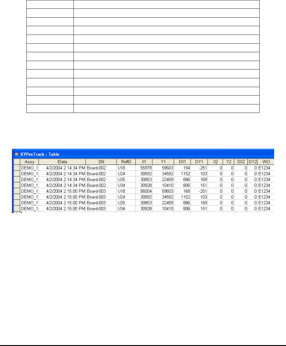
Sample Data Output
The XY Positions are sent via the ODBC to a separate table named XYPosTrack. The table has
the following fields:
Assy
Recipe Name
IDate
Inspection date and time stamp.
SN
Serial number of the board inspected.
RefID.
Reference designator for the part
X1
X reference position for the first mark
Y1
Y reference position for the first mark
DX1
X Offset position for the first mark
DX2
Y Offset position for the first mark
X2
X reference position for the second mark of the same part
Y2
Y reference position for the second mark.
DX2
X Offset position for the second mark.
DY2
Y Offset position for the second mark.
WO
WorkOrder
NOTE
All positioning units are in microns.
Here is a sample output.
Operational Details
Marking inspection uses a search algorithm called Normalized Grayscale Correlation or in
layman terms “template matching”. All successful template matches generate an XY position of
the successful match. We call this XY position the “Found” position. A deviation is calculated
by subtracting the trained position from this found position. It is this deviation that gets stored
into the database as X and Y.
Each part can have one or more mark inspection boxes. If the part has only one mark inspection
box, only the X1 and Y1 fields in the database table will be filled. X2 and Y2 are for the second
mark inspection box. Having a pair of XY data points allows for the calculation of the rotational
deviation of a placement.

SPC Data Logging 15-7
Mark1 Mark2
Using Edge Locators for Position Tracking
In addition to using pattern matching you can also use the Edge Locator algorithm for position
tracking. Edge locator provides more accurate position tracking on targets with clear and well
defined horizontal and vertical edges. To use Edge locator for position tracking, train two marks
with the Edge Locator algorithm. The first mark should be trained to locate a vertical edge or
strip and the second mark should be trained to locate a horizontal edge or strip. The first mark
will provide the X position plus the angle data and the second mark provides the Y position data
to the database.
15.5 Robust Mode for Data Logging
In the normal operating mode for data logging, the software opens a link to the database during
software start-up and assumes the link to be there for all the subsequent data logging operations.
This mode of operation works well for most of the network environment. In environments where
the network traffic is heavy and a prolong connection to one computer cannot be guaranteed, the
YesAX software offers a more robust mode of data logging. In the Robust Mode, the software
tests the database connection before each batch of data logging operations. It is slightly slower
but far more reliable. To enable Robust Mode, edit the YesAX.ini file:
[ODBC_Report]
..
RobustMode=1
15.6 Process Alarm
YesAX allows users to setup various trigger conditions to raise process alarms. There are
currently two types of alarms, rate alarms and defect alarms. The rate alarm triggers when the
defect rate or the false call rate exceeds a preset level. The defect alarm triggers when a user-
specified defect condition has been reached.
15.6.1 Rate Alarms
The Rate Alarm triggers when the defect rate or false call rate exceeds the preset level. The
defect rate is measured as PPMO (Part Per Million Opportunities) and is calculated as:
Defects
-------------------------------- * 1,000,000
Opportunity for Defect
The opportunity for defects is the total number of tests performed. It is usually the sum of
Marking, Lead Bank, and Solder inspections.
The false call rate is also measured as PPMO and is calculated as:
False Call Count
-------------------------------- * 1,000,000
Opportunity for False Call

15-8 SPC Data Logging
On a board with no real defects, the opportunity for false calls is the same as the opportunity for
defects. To simplify the calculation we assume the opportunity for false calls also as the sum of
Marking, Lead Bank, and Solder inspections.
A high defect rate would indicate problems upstream. A high false call rate may indicate the
inspection recipe should get additional tweaking.
15.6.2 Defect Alarms
The defect alarm triggers when the user-specified defect conditions are exceeded. There are 10
defect alarms. You can set one defect alarm to trigger when there are more than 3 part defects in
the last 5 runs of boards. You can set another defect alarm to trigger when there are more than 10
solder defects in the last 3 runs of boards.
The first step to setup a defect alarm is to group the defects into classes. This is done by editing
the defect.ini file. Use the @C# notation to assign a class to each defect. The class number starts
with 1 and ends with 9. Defects with no class assignment default to class 0. Here is a sample
defect.ini file with the class assignment.
[01] Unclassified
[02] Missing Part@S@C2
[03] Wrong Part@S@C1
[04] Tombstone Part@S@C4
[05] BillBoard Part@S@C2
[06] Skew Part@C2
[07] Wrong Polarity@S@C3
[08] Lead Solder Bridge@C4
[09] Bend Lead@C4
[10] Insufficient Solder@C4
[11] Solder defects@C4
[12] False Call
After setting the defect classes, setup the trigger condition by selecting Process Alarm.. from the
System menu. The Process Alarm Setup dialog displays.