YesAX V3.1.2 - Software User Manual.pdf - 第65页
Recipe Creation Step by Step for 2D Re cipes 6-7 The Align CAD Coordinates dialog display s. Move the highlighted ROI (region of interest) in the video window, on top of the corresponding part and then click OK . When th…
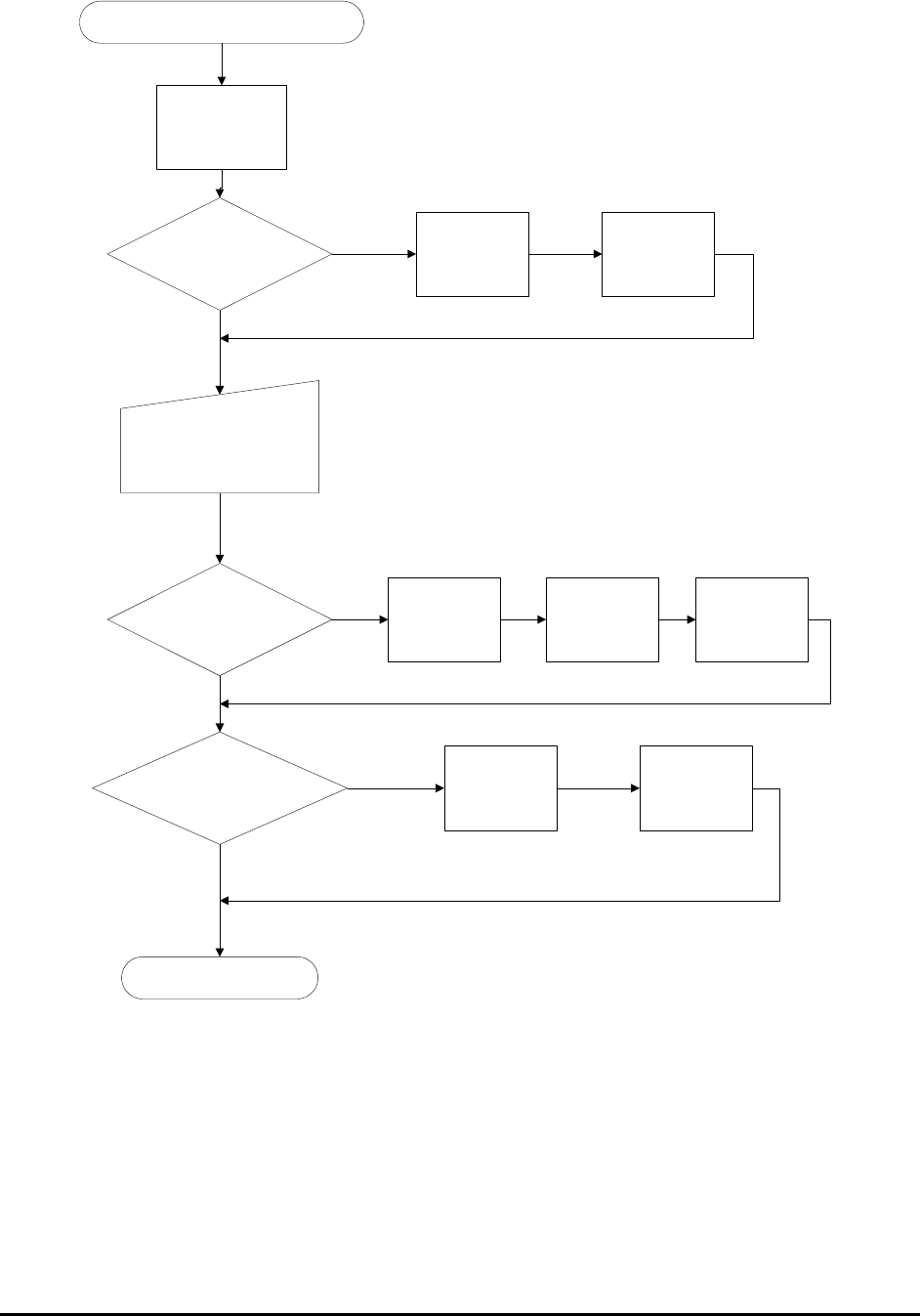
6-6 Recipe Creation Step by Step for 2D Recipes
New Board Dialog Close
Define the Bottom
Left Corner
Board Size Info in CAD data?
User Want to Capture?
Prompt User to Capture board
Image Set
Launch the Grid
Image Set Dialog
Alignment Mark Info. in the CAD
Data ?
Capture Board
Image Set
Create Map
Background
Define bottom
right corner
Define top left
corner
Define Left
Alignment Mark
Define Right
Alignment Mark
Proceed to CAD Import
Yes
No
Yes
No
Yes
No
6.3 Step3: Import CAD data
The software analyzes the part position information from the CAD data and sequentially
positions the camera over three parts on the board. The objective is to verify the position of that
part. The first part selected by the system is the one closest to the bottom left corner of the board
(the systems origin) interpreted from the CAD data. Next is the part closest to the bottom right
corner of the board and finally the part at the top left corner of the board. For each part, the
camera will focus over the corresponding corner it thinks the part should be in.
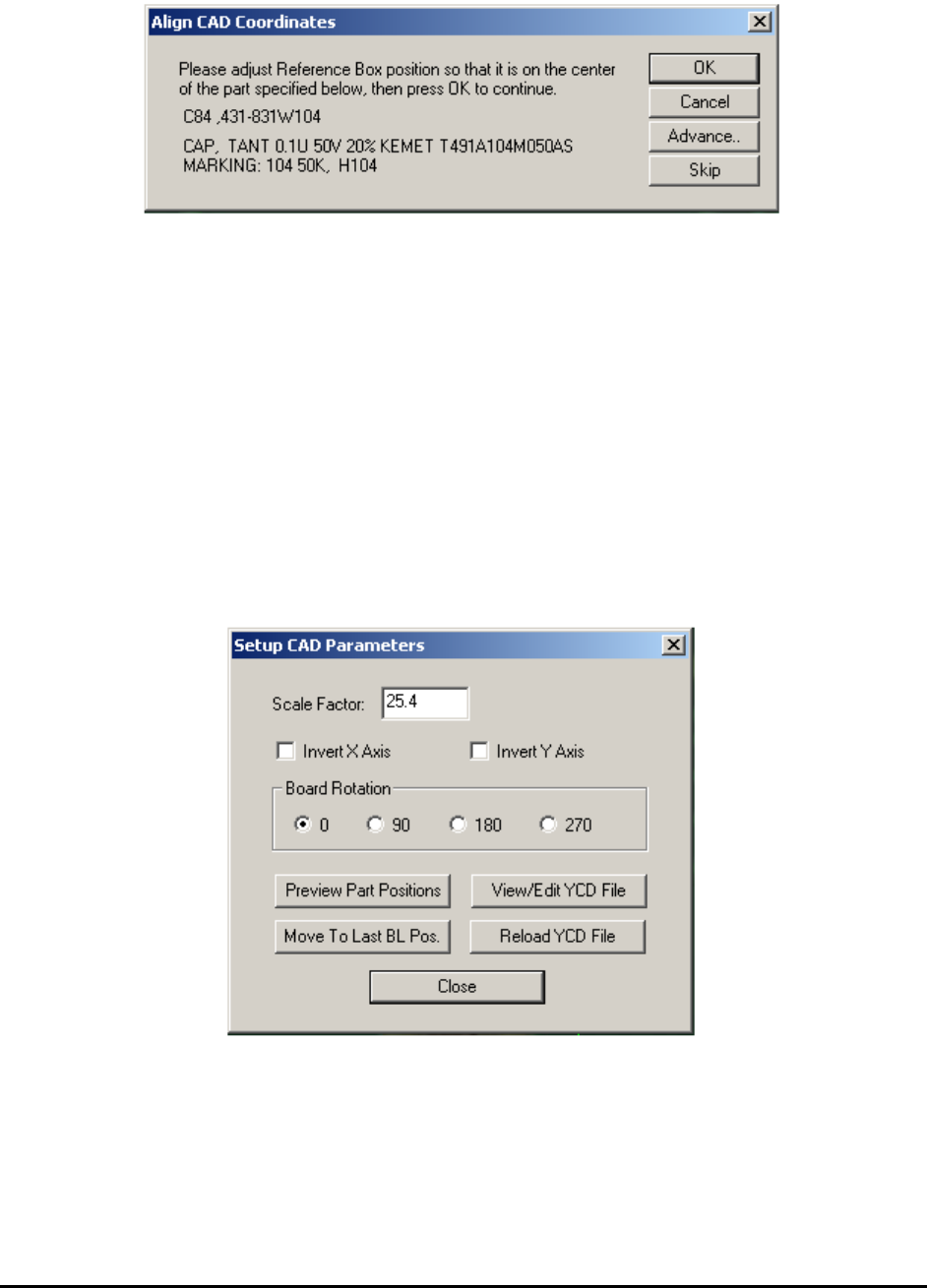
Recipe Creation Step by Step for 2D Recipes 6-7
The Align CAD Coordinates dialog displays.
Move the highlighted ROI (region of interest) in the video window, on top of the corresponding
part and then click OK.
When the OK button is clicked, the software records the part position. Based on the part position
of the three parts located on the extreme corners of the board, the software compensates for any
differences in the coordinate systems between the system that generated the CAD data and the
system reading it. The factors compensated are XY scaling difference, board rotation and XY
axis skew. The Skip button on the dialog allows the user to select a different reference part. It is
recommended to select a small part, such as a chip, as a reference part because for big parts it
becomes more difficult to determine the center position. Also during this process you can use the
Shift-Ctrl and Arrow keys to move or re-size the box for more accurate alignment, if needed.
If the prompted part is not at the supposed corner of the board, the CAD data header information
may be incorrect in describing the CAD data. Pressing the Advance.. button launches the Setup
CAD Parameters dialog that allows you to adjust the coordinate system of the CAD data.
6-8 Recipe Creation Step by Step for 2D Recipes
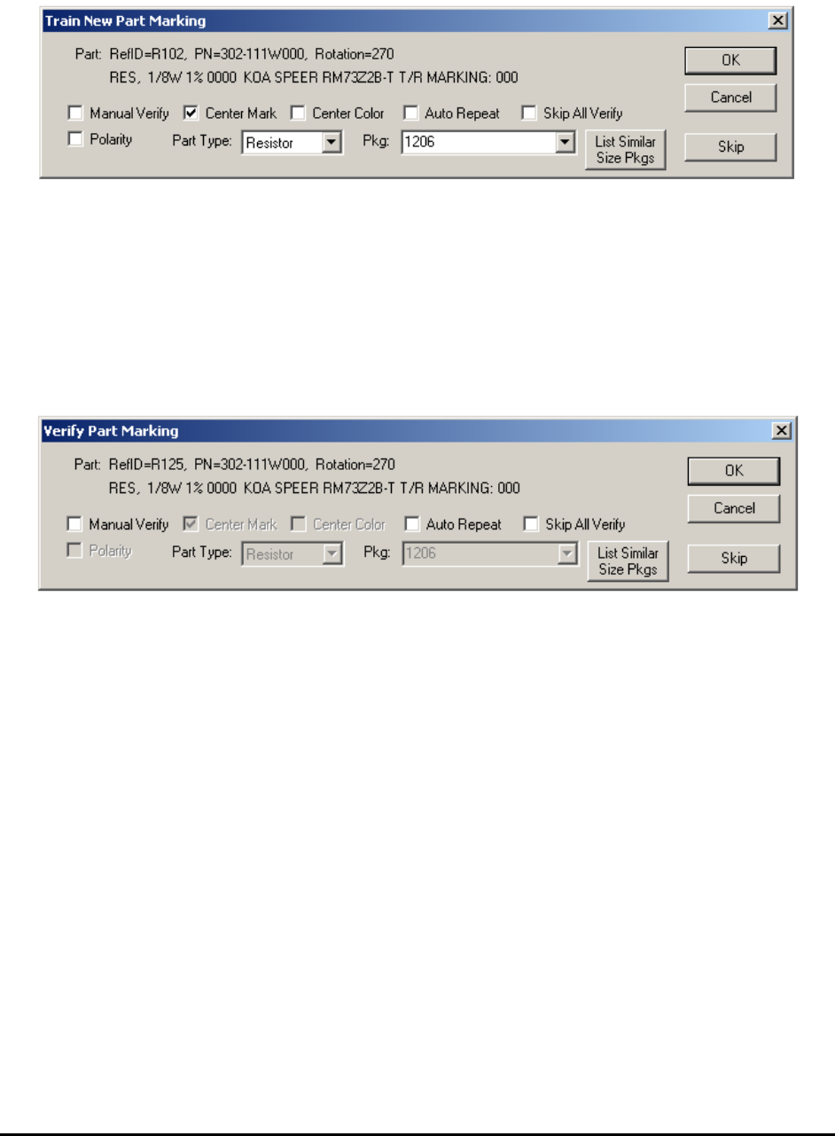
After the coordinate system is adjusted, the system will move the camera to view each part one
by one. You are prompted by the Train New Part Marking dialog on every new part to train.
Verify and/or modify the Polarity and Center Mark checkboxes for the part’s marking if
needed. Select the correct Part Type and Package type for the part. The Package selection list
changes with the selection of Part Type. For example if Part Type resistor is selected, only the
packages for resistors will be listed. To have the software list all the available packages, select
Misc. for part type. If the correct package cannot be found, NO_PKG should be selected for
package. if you press the Skip button, the system will skip training the part and result in the part
NOT being inspected.
If the part in the CAD data is already in the part library, the Verify Part Marking dialog appears.