YesAX V3.1.2 - Software User Manual.pdf - 第164页
11 - 20 3D X-Ray Inspection Methodolo gy Save Height Info. to File when executed will save the measurement results of every laser references together with the relate d info, e.g., X/Y location, ref ID, etc… to ZMap.txt f…
3D X-Ray Inspection Methodology 11-19
All functions related to future site are included in this dialog box. The Add Site, Move to Next
and Delete Site are used to add a future site, navigate to next future site and delete a future site in
current location. The “Capture Image Set” function will allow user to capture image set for
future site only. After that all future sites will change to normal 3D sites and all red crosses
(which represents the location of future sites) inside map view window will change to white
circles automatically. The Show 3D Site in Video View checkbox if checked will display the
inspection area of all sites (normal and future) in video view. The feature is useful during recipe
debug when the software complains about certain 3D inspection boxes are not included in any
3D site.
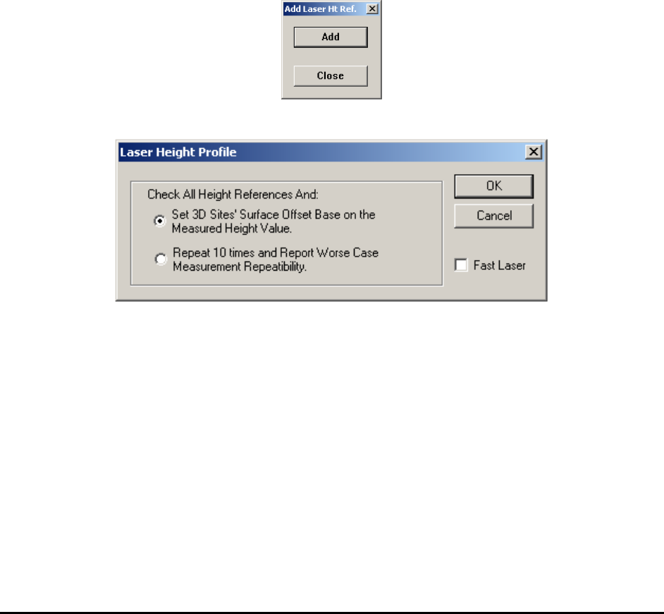
Add Laser Reference … function provides user a quick and easy way to allocate laser
references on board surface, instead of train laser references as regular parts. To start user needs
to execute this function and launch the Add Laser Ht Reference… dialog.
To add a laser site, all user needs to do is to move the stage to the desired location and click the
Add button. The laser reference will be added to the list automatically. It is advisable to test the
laser and adjust the position after adding the laser reference sites. The user can keep adding laser
sites by clicking the Add button. Clicking the Close button will dismiss the dialog.
Profile Board Height when clicked will launch the following Profile Board Height Dialog.
There are two options available. The first option “Set 3D Site’s Surface Offset Based on the
Measured Height Value” when selected will run all available laser references measurement
once and update the board offset number as well as the surface height, pitch and roll information
for each 3D site. The second option “Repeat 10 times and Report Worse Case Measurement
Repeatability” when selected will run all available references 10 times and calculate statistics
for each reference. When finish the test another dialog box will show up and report the IDs of
laser references which have the best and worst statistics. If the worst statistics doesn’t look good,
it is advisable to go back to that particular location and fine tune laser reference setup parameters
or even re-adjust the position of that laser reference site. The second option is mostly used for
diagnosis and recipe program debugging purpose.
Re Sequence Laser Ref. by default during inspection the software executes the laser reference
in the sequence that it was created. This menu selection allows user to adjust this sequence. This
is an interactive feature very similar to the Re Sequence Sites feature discussed above.
11-20 3D X-Ray Inspection Methodology
Save Height Info. to File when executed will save the measurement results of every laser
references together with the related info, e.g., X/Y location, ref ID, etc… to ZMap.txt file under
current recipe folder.
Show Only Current Site IBs is a display flag user can toggle on or off. Turn it on if you want to
find out which inspection box (IB) is inspected in which site.
Inspect 3D in Dry Mode, 3D inspection is generally slow, complex boards can take many
minutes to inspect. During inspection recipe fine tuning it may need to inspect the same board
many times to determine the optimal inspection parameters. The Dry mode speed up the process
by skipping the image capturing steps; without image capturing 3D inspection is about the same
speed as the 2D inspection. User can use dry mode only when the same board is inspected
repeatedly and when there is no change to X-ray power levels.
Capture IS for Offline Program (Capture Inspection Path Image Set for Offline Programming).
This feature capture an Inspection path Image Set (as oppose to Grid Image Set) before 3D
inspection boxes are defined. This is important because it allows the time consuming portion of
the recipe development process, defining 3D inspection parameters, set 3D site offset, etc to be
done offline line without consuming machine time.
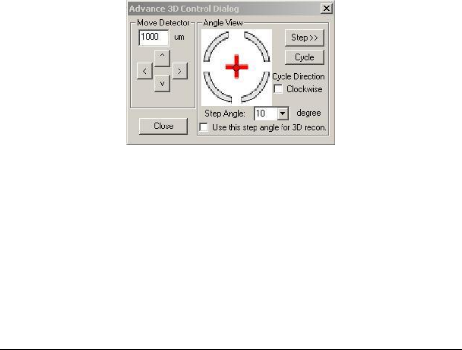
11.7 Advance 3D Options
Click the Advance 3D Options in the menu above will launch the Advance 3D Control dialog,
as showing below. These are really advanced options and should be operated by person with
deep understanding of 3D X-Ray only.
Move Detector: Clicking the arrow button once will move the position of X-Ray detector to that
direction with amount specified in open field. This function is used for diagnostic and calibration
purpose by factory engineer only.
3D X-Ray Inspection Methodology 11-21
Angle View: The default step angle between each side angle views are 45°, which indicates
totally 8 (360/45) side angle images will be used for 3D reconstruction. However, this step angle
could be changed in this Angle View section. For inline inspection the step angle can be changed
to 90° so only 4 (360/90) side angle images will be used for reconstruction. In this case the
inspection speed will be doubled but the reconstructed slices may not have as good quality as
those slices reconstructed by using 8 angle images. Normally 4 side angle images are only used
for 3D sites without much overlap between top side components and bottom side components.
The step angle could also be changed to a number higher than 8. Sliced reconstructed with more
side angle images will have better image quality. Higher angle image numbers can only be used
for manual inspection purpose and cannot be applied to inline 3D programming. Whenever user
makes a change to the number of step angle, the Use this step angle for 3D recon. checkbox
must be checked to take effect. When sample board is right at certain 3D site, the change of step
angle number may affect setting of current 3D site. So please be very careful when use this
options.
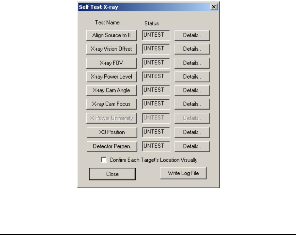
11.8 3D Related Calibrations
3D inspection is much complicated compare to normal 2D inspection. It requires high precision
of moving and full calibration of X-Ray cameras. The basic steps of X-ray calibration on X3
AXI systems are similar to X2 AXI systems but with some differences and some extra steps. The
same calibration board is used for both X2 and X3 X-ray test. The Self Test X-ray dialog is
shown below.