YesAX V3.1.2 - Software User Manual.pdf - 第134页
10 - 40 General Inspecti on Methodolo gy 10.5.3 Solder Inspection Solder inspection for BGA balls is designed to verify the solder ball quality on each individual ball of a BGA device. The default inspection uses a BGA A…

General Inspection Methodology 10-39
The Show Reference button displays the reference image, the Capture Reference Button
capture the reference image from the camera. The Show Difference button displays the
Difference Image. The Reference ID shows a number which represent the ID of that reference
image. This number is similar to the template number in template match inspection. A Reference
ID shows 0 means the reference image haven’t been captured yet.
Because of the perspective distortion which is common in the X-ray images, the Reference
Image has to be captured exactly where the part is to be inspected. In other words, if the part is to
be tested near the top left corner of the screen, then the Reference Image should be captured at
that screen location. The In Next Run Capture Images as Reference checkbox switches on the
reference capture mode, in capture mode in the next inspection run the software will capture
reference images for all test boxes using image subtraction algorithm. User should make sure a
good board is put in before the inspection run. The checkbox is turned off at the end of the
inspection run, normal image subtraction will resume.
During review process the software always displays the Reference image; user can optionally
select to have the different image also displayed. To select the option check the Show Difference
Image During Review checkbox.
By default each lead inspection box with Image Subtraction algorithm setup will have one
unique reference image/ID. Sometimes it is convenient to have the same lead box of different
parts with same part number share the same reference image. To do that the user needs to check
the Same Reference for Different Parts checkbox.
10-40 General Inspection Methodology
10.5.3 Solder Inspection
Solder inspection for BGA balls is designed to verify the solder ball quality on each individual
ball of a BGA device. The default inspection uses a BGA Analysis algorithm to detect
insufficient solder, bad shape, gray defects and void defects. Since this algorithm also utilizes
measurements from the BGA Group algorithms, make sure that solder inspections run after lead
bank inspections.
After the solder inspection box is created, display the solder pop-up menu by pressing the right
mouse button while pointing inside the solder inspection box.
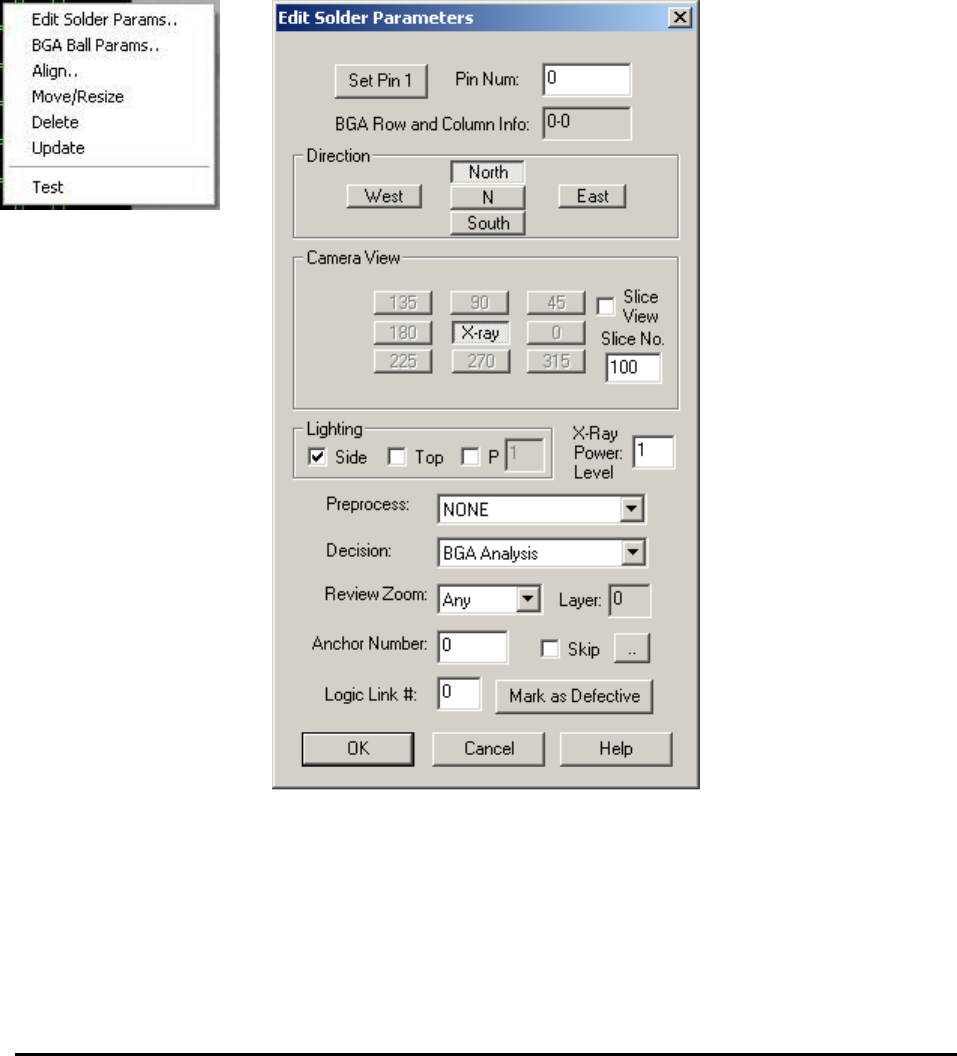
Edit Solder Params. launches the Solder Parameters dialog
Enter the current solder pin number in the Pin Num field.
The rest of the buttons on the dialog set the Direction, Camera View, Slice View, Slice No.,
Lighting and X-Ray Power Level for the inspection. For X-Ray inspection the Camera View is
always set as X-ray, the Lighting is always set to Side and the X-Ray Power Level needs to be
specified in the corresponding field.
General Inspection Methodology 10-41
For X-Ray inspection of BGA solder, there is no specific preprocessing algorithm and the
decision algorithm is always set as BGA Analysis.
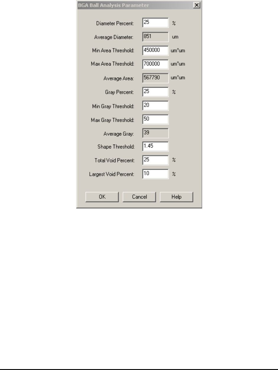
BGA Ball Params.. launches the BGA Ball Analysis Parameters dialog.
This setup dialog box provides information about Average Area, Average Diameter and
Average Gray of all BGA solders belonging to the same lead bank. Based on these
measurements, define two percentage thresholds: Area Percent and Gray Percent. Area defect
classifies any BGA solder with too much or too little area, compared to the average area of all
the balls in the group. Gray defect identifies any BGA solder with too low or too high of a gray
level.
The shape score of BGA solder indicates the roundness of the solder ball. The perfect round
shape ball will have a shape score of 1.0. In reality all balls will have a score above 1. The higher
the score is, the more irregular shape the ball has. Setup the Shape Threshold to pick up those
balls with a bad shape.
The Total Void Percent and Largest Void Percent threshold needs to be set by the user to pick
up void defects. Any BGA solder ball with a higher total void percentage value or a higher
largest void percentage value (compared to these two threshold values) is considered to have a
void defect. The default values for these two parameters are 25 and 10, respectfully.