YesAX V3.1.2 - Software User Manual.pdf - 第286页
29 -2 Specificat ions 29.3 System Specifications Table 29 -2 provides general specificat ions for the sy stem s. Table 29 -2 Syste m Specific ations Specificatio ns Throughput Up to 4 sq. in./sec. > 500,000 com ponent…
Specifications 29-1
29 - Specifications
29.1 Overview
The Nordson YESTECH AXI Systems’ facility requirements and specifications are listed in Table 29-1.
These specifications are intended as a convenient reference for installation, system relocation, planning
and operation. Meeting the requirements will ensure reliable operation and safety of the AXI system.
WARNING! CAUTION!
To ensure optimal performance and safety, it is necessary to install the coating
system in a facility that meets the requirements listed in this chapter. If you have
any questions, please contact Nordson YESTECH Technical Support.
29.2 Facility Requirements
The AXI Systems are designed for indoor use only. Table 29-1 provides general facility requirements for
the systems.
Table 29-1 Facility Requirements
Facility Requirements
System Footprint
83” x 83” x 81” (2110mm x 2110mm x 2060mm)
System Weight
4,842 lbs (2241 kg)
Air Input
30 psi MIN., 1/4” air hose. 2 CFM, 100 psi MAX
Main Power Supply
110VAC (220 optional) 50/60 Hz, 15 amps
Short Circuit Current
Rating (SCCR)
10kA
29-2 Specifications
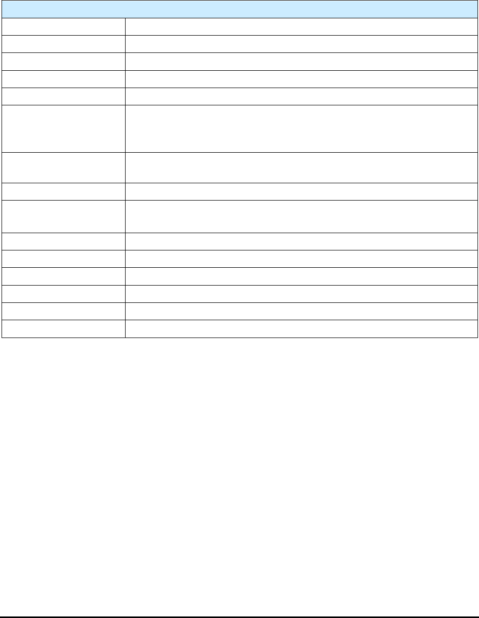
29.3 System Specifications
Table 29-2 provides general specifications for the systems.
Table 29-2 System Specifications
Specifications
Throughput
Up to 4 sq. in./sec. > 500,000 components per hour
Max. Board Size
23” x 18” (580mm x 460mm)
Clearance
2” (50mm) top and bottom
Min. Component Size
0201; 01005 with high magnification option
False Calls
<500 PPM (<0.05% typical)
Defects Detected
Part: position, missing, wrong, polarity, skew, tombstone
Lead: bent, lifted, bridging
Solder: open, insufficient, short, solder balls
Material Handling
SMEMA, dual direction auto width conveyor, pass / fail signals, board
clamping
Lighting
Proprietary Fusion Lighting multi-angle LED
Imager
1 mega pixel color camera, 1 mega pixel X-ray camera
25, 12 or 6 micron pixel size
Noise
<70dBA, 76 db peak @ 1 M
Ambient Air Temp
41°F to 122°F (5°C to 50°C)
Max Relative Humidity
< 90% non-condensing
Altitude
5280 feet (1609 meters)
CE Certification
Yes (see
SECSII \ GEM Interface
Option
Specifications 29-3
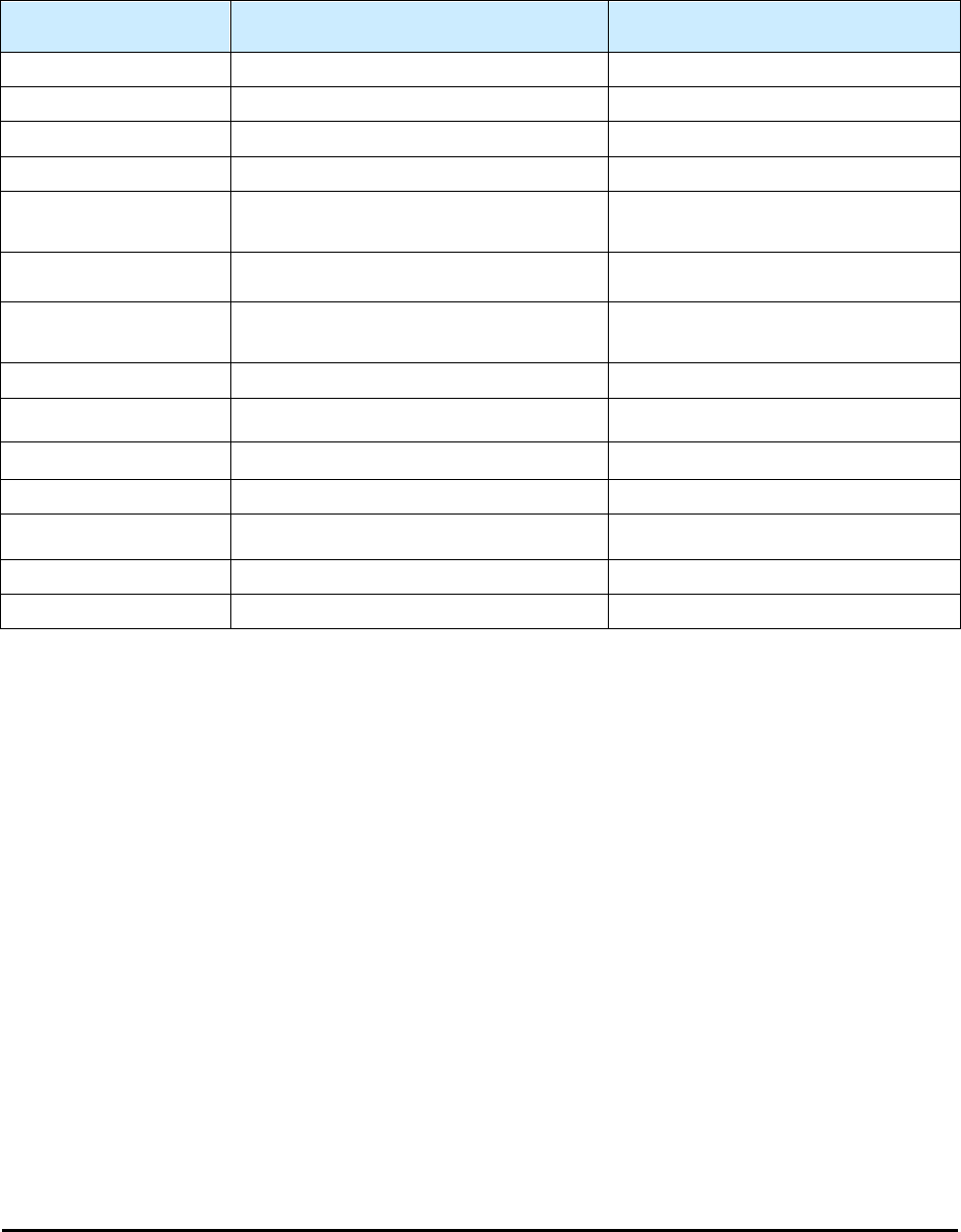
29.4 Laser Height Sensor Specifications
Table 29-3 provides laser height sensor specifications for the systems.
Table 29-3 Height Sensor Specifications
Laser Height Sensor
Laser Height Sensor
for Transparent, Reflective Surfaces
Probe Activation Force
NA
NA
Probe Tip Diameter
NA
NA
Probe Retract
NA
NA
Laser Classification
Class 2
Class 2
Light Source
Semiconductor Laser <1 mW,
670 nm (red)
Semiconductor Laser 1 mW,
670 nm (red)
Spot Diameter
700 µm at reference distance of 55 mm
7 µm at reference distance of 30 mm
Reference Distance
and Range
55 mm ± 10 mm
(2.2 in. ± 0.4 in.)
30 mm ± 1 mm
(1.2 in. ± 0.04 in.)
Ambient Light
4,000 lux max.
10,000 lux max.
Sampling Rate
1 kHz
1 kHz
Dynamic Resolution
10 µm
10 µm
Repeatability
± 25 µm @ 3s
(See Note 1)
± 25 µm @ 3s
(See Note 3)
Accuracy
1
± 50 µm @ 3s
± 50 µm @ 3s
Sensing Range
20 mm (± 10 mm)
(see Note 2)
20 mm (± 10 mm)
Operation Mode
Range-finding
Plunge
1
Measured on a white ceramic dispense card (card properties: 96% roll compacted Alumina, flatness 0.003-in. per
linear inch, .8 µm Ra value).
2
Measured from the top of the conveyor rail. The sensing range is 10-mm above and 10-mm below the top of the rail.
If a customer’s height-sense location is 10-mm above the conveyor rail, the LHS will not focus (contact the factory;
a special is required).
3
Measured on a reflective surface.