YesAX V3.1.2 - Software User Manual.pdf - 第75页
3D Recipe Creatio n 7-5 The conversion process for the ConvertGenCAD utility is similar to other conversion utility. ConvertGenCAD generates a total of 2 YCD files and 1 YPC files. BoardName_TOP.YCD and BoardName_BOT.YCD…
7-4 3D Recipe Creation
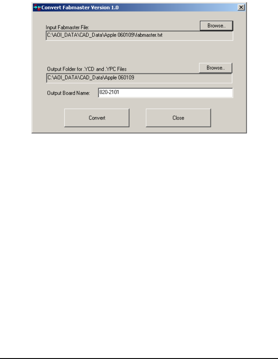
7.2.2 ConvertFM Utility
FabMaster is a common CAD format. It contains detailed information of the board. The
ConvertFM program reads the FabMaster text file and generates .YCD and .YPC files. The user
interface is simple, as shown below.
The conversion process for the ConvertFM utility is the same as for the Convert5DX utility.
ConvertFM generates a total of 4 YCD files and 2 YPC files.
BoardName_Full_T.YCD and BoardName_Full_B.YCD are YCD files for top and bottom
side of the board with all the parts in them.
BoardName_BGA_T.YCD and BoardName_BGA_B.YCD are YCD files for top and bottom
side with only BGA parts plus the parts needed for CAD alignment (parts near the corners of the
boards). Copy and paste additional parts from the BoardName_Full_x.YCD file into the
BoardName_BGA_x.YCD if more parts are needed to be imported.
The two YPC files are BoardName.YPC and BoardName_Sorted.YPC.
7.2.3 ConvertGenCAD Utility
GenCAD is another common generic CAD format. A GenCAD .cad file contains detailed
information of the board. The ConvertGenCAD program reads the GenCAD .cad file and
generates .YCD and .YPC files. The user interface is simple and very similar to other conversion
utilities.
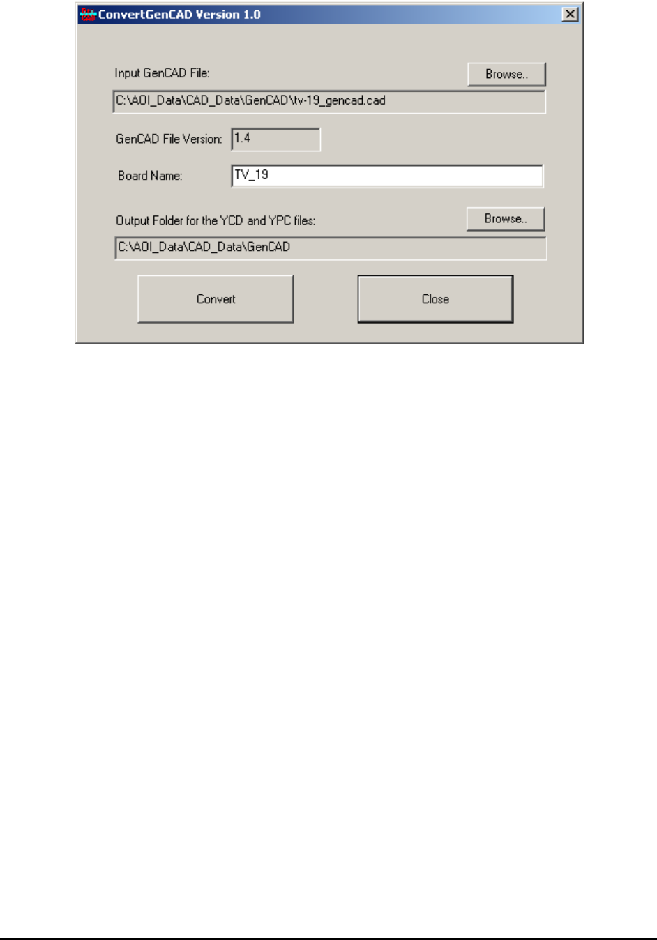
3D Recipe Creation 7-5
The conversion process for the ConvertGenCAD utility is similar to other conversion utility.
ConvertGenCAD generates a total of 2 YCD files and 1 YPC files.
BoardName_TOP.YCD and BoardName_BOT.YCD are YCD files for top and bottom side of
the board with all the parts in them.
The YPC file is BoardName.YPC.
7.3 Creation Process When Machine Time is Unlimited
7.3.1 Step1: Prepare CAD Data
CAD data can greatly speed up the recipe creation process. If the board to be inspected has more
than 20 parts, it is important to insist on getting the proper CAD data before starting the recipe
creation process. We currently have conversion utilities to automatically convert from 5DX NDF
format, GenCAD format, and FabMaster CAD format to the proper data formats (YCD and YPC)
for YesAx import. CAD data can also be manually converted using Excel or other text
formatting utilities.
7.3.2 Step2: Determine Which Side Faces Up
The side with the most critical components that require 3D inspection should face up.
7.3.3 Step3: File, New Board
In this step we define the board size and train the fiducials. Also capture a 5% visual image set to
create the board background image for the recipe. Do NOT import CAD data in this step.

7-6 3D Recipe Creation
7.3.4 Step4: Create Test 3D Sites and Verify Board Thickness
This step is very important for complex boards when a lot of surface parts (resistors and
capacitors) on both top and bottom sides need to be inspected. For some simple boards this step
is optional. Manually add one or more 3D sites and make sure the Bottom button in the Edit 3D
Site dialog brings you to the correct surface slice at the bottom side of the board. If not, adjust
the board thickness parameter in the Video Parameters dialog.
7.3.5 Step5: Import Centroid CAD for BGA parts
The CAD conversion utility creates two sets of YCD files, Full and BGA only. Import the BGA
only file. There is no need to set the proper part size for the BGA parts. The part size will be set
in the next step when YPC CAD is imported.
Press the “Skip Mark” button.
In this step all we need is to have small purple boxes to show the centroid of the BGA parts.
7.3.6 Step6: Import Pin CAD, and merge Pin library Data
The Pin CAD (YPC file) contains the position for each pin (solder joint) of every part. During
the process you can merge the Pin definition from the Pin library with the pin location and name
from the YPC file. Merging the Pin definition is highly recommended, even if you cannot find an
item in the pin library that matches your part exactly. This is because once a link is established
between the part and the pin library, future changes will be a lot easier.
NOTE
you CANNOT use any solder with the BGA Solder algorithm in any item in the
Pin library.
7.3.7 Step7: Walk Thru and Create 3D Sites for the BGA Parts
Assuming you completed step 6 accordingly, this step would create the 3D sites for BGA parts
almost automatically. Select Walk Thru Parts w/o Sites in the List View Selected pop-up menu.
At each part, select Create 3D Sites, From Parameter dialog.” to select the proper parameters.
Then press OK. After the sites are created, select Update from the part menu to propagate the
3D sites by PN or Package.
After finishing the walk through, select Re-Capture All Sites from the pop-up menu of the 3D
Control dialog to convert all the Future Sites to normal 3D sites.
7.3.8 Step8: Add Laser Height References
One laser height reference can be added with one mouse click.
Select Add Laser Reference.. from the pop-up menu of the 3D Control dialog.
After all the laser references are added, select “Profile Board Height” from the same pop-up
menu.