YesAX V3.1.2 - Software User Manual.pdf - 第151页
3D X-Ray Inspection Methodolo gy 11 -7 Delete Slice button will allow user to delete the selected slice from slice list with one click. Please make sure to highlight the slice in slice list first bef ore clicking Delete …
11-6 3D X-Ray Inspection Methodology
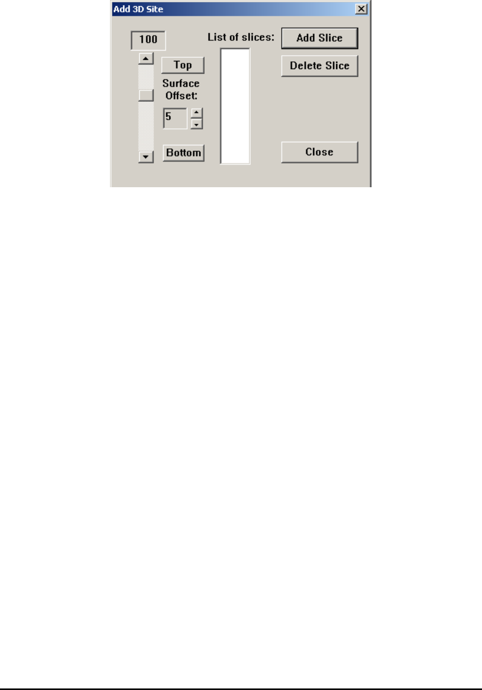
Current slice level is shown in top left corner. For Add 3D Site dialog, 0 (as representing the top
side of the board) will always be shown at first time.
The slider bar on left allows user to adjust current slice level and update the slice view on
screen. Click the up and down arrow will change slice level one at a time and click on the empty
space between slider bar and arrow button will change slice level at the step of 10. The user can
also hold the slider button and change slice level to any number between -300 and 300.
Top and Bottom buttons indicate the slices correspond to board top surface and bottom surface.
Board top surface will always have a slice number of 0. Depends on the board thickness and the
current FOV, default bottom slice level will be calculated automatically. The distance (in Z axis)
between each slice depends on the FOV. For 1” FOV, the distance is 1 mil (0.001 inch or 25.4
um). For 0.5” FOV, the distance is 0.5 mil (0.0005 inch or 12.7 um). So if current site is in 1”
FOV and the board thickness is 60mil, the default slice level for bottom side board will be -60.
Sometimes the measurement of the board is not perfect and the slice level for bottom side of
board may not be at the exact number as calculated. It is recommended to fine tune the bottom
side slice level. Once the best number has been found the same number should be used for
different site, for consistency purpose.
Surface Offset defines the offset number for current 3D site. Ideally the slice at 0 should give
the best result for top slice of the board. But for multiple reasons slice number 0 does not
necessarily represent the best slice. These reasons include board warp, board clamping,
component location and others. Since slice level 0 is used for top slice at any time, an offset
number needs to be introduced and offset the actual height change. To adjust the surface offset
number, user always need to put slice level at 0 first and then adjust the surface offset number to
get the best slice for top side of the board.
List of Slices shows a list of slices have been added to current site. This list can hold up to 10
different numbers for each 3D site. Normally 2 slices is required for board inspection, one
represents top side and the other one represents bottom side.
Add Slice button will allow user to add the current slice level to slice list with one click. Please
note that information of current 3D site won’t be added to recipe if no slice’s been added to slice
list before the Add Slice dialog’s been closed. For people only want to take a look at slices at
different level and don’t want to add current 3D site to list, use Add Slice dialog without adding
an actual slice will be a good idea.
3D X-Ray Inspection Methodology 11-7
Delete Slice button will allow user to delete the selected slice from slice list with one click.
Please make sure to highlight the slice in slice list first before clicking Delete Slice button.
Close button will close Add Slice dialog. If at least one slice’s been added to slice list, current
3D site information will be saved to recipe. A white circle will appear on map view window at
the current place, representing the 3D site’s been just added. All the information related to 3D
sites (FOV, power level, X/Y position, slice offset and number of side angle images) will be
saved in Slice.x3d file, which is saved in current recipe folder.
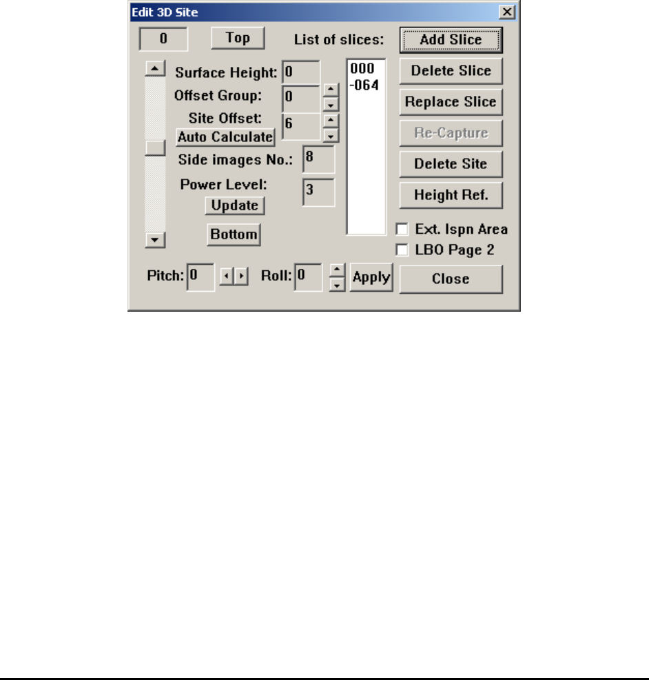
11.4 Edit 3D Site
Once a 3D site has been defined and added to the list, the user can move the stage to the position
of that site first and launch the Edit 3D Site dialog. This dialog is similar to Add 3D Site dialog
but with lots more options.
Add Slice and Delete Slice are similar to the one in Add 3D Site dialog.
Replace Slice allows user to replace current slice with a different number. To do that user needs
to highlight the slice number in slice list first, then move the slider bar or click the up/down
arrow and pick a different slice number. Once Replace Slice button’s been clicked, software will
prompt user to confirm replace slice. If user clicks YES the highlighted slice number will be
replaced by a different one user just specified.
Re-Capture will capture another angle image set and use this set for image reconstruction.
Delete Site will delete the current site and also remove it from the site list.
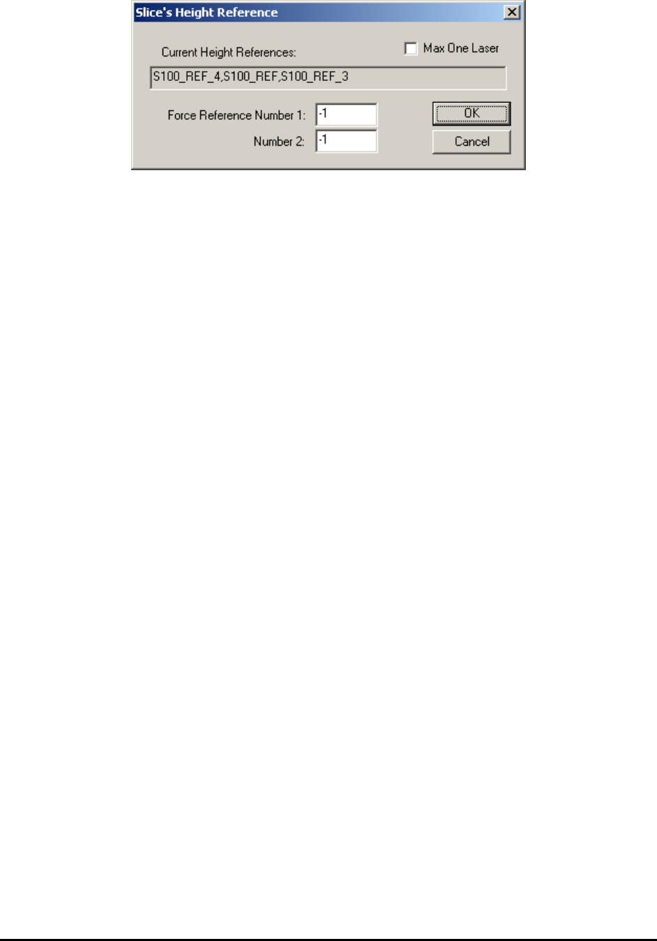
Click the Height Ref. button will launch the Slice Height Reference Dialog. To understand the
features mentioned here, it is better for user to read through next section, Laser Height
Measurement first then go back here and finish reading.
11-8 3D X-Ray Inspection Methodology
The first time the dialog shows up, both Force Reference Number 1 and 2 are -1, which means
software choose laser references for this site automatically. The laser reference IDs been used by
current 3D site is shown in the Current Height Reference field. In this case, the original list
contains: S100_REF_4, S100_REF_1 and S100_REF_3. If user type in 4 in the Force Reference
Number 1 field and click OK to close the dialog. The user also needs to close the Edit 3D Site
dialog and move around a little bit then go back to current 3D site. Once he opens the Slice’s
Height Reference dialog again, the S100_REF_5 will be added to the list and replace
S100_REF_3, which is at the end of this list. If there are less than 3 laser references in the
original list, the new force reference ID will be appended to the list. The user can type in two
different numbers in Number 1 and Number 2 field so the software will include both laser
references in the list. For multi-panel board, the force reference ID will have the same block ID
as the current 3D site has. For example, the current block ID is 03 and user types in 15 in the
field, in this case the full name of the laser reference being added will be 03_S100_15. When
using this option, the user needs to be careful and avoid choosing laser reference which is too far
away from current 3D site. If Max One Laser checkbox is enabled, only one laser will be used
for current 3D site. This will either be the laser site closest to center of current 3D site or the
laser specified in the Force Reference Number 1 field. If the area around current 3D site is
relatively flat, it is ok for the user to use one laser only to save inspection time.
Surface Height indicates the height of current 3D site’s center point. If there is more than one
laser references allocated for current site, this number will be calculated automatically based on
height information of these laser references. Otherwise, a number 0 will be assigned to height
offset. Ideally the height offset of every 3D site will be about 0. Due to board warp and other
board handling issues (i.e., use of a board fixture or loader) normally the height offset won’t be 0.
Here a positive number means the center of current 3D site is higher than board top surface and a
negative number means the center of this 3D site is lower than board top surface.
Site Offset indicates the height offset of current slice compare to board top surface. If
components are right on top side or bottom side, the surface offset number will be very close to 0.
For components like BGA, the surface offset won’t be 0 and needs to be adjusted manually to get
the best effect.
Side images Num indicates the number of images used for reconstruction. Default number is 8,
which means that 8 angle image shots will be taken starting from 0° to 315° with 45° intervals.
For inline program another choice is 4. In this case only 4 angle images will be taken starting
from 0° to 270° with 90° intervals. For offline/manual inspection mode there are more choices.
The detail wills be covered in the 3D advance options section.