YesAX V3.1.2 - Software User Manual.pdf - 第118页
10 - 24 General Inspecti on Methodolo gy Current ly the re are seven decision algorithm s for the solder inspection box: Histogram Inspection , Pattern Matching, BGA Analysis, BGA Pin Inspection, Solder Blob Analysis, Pe…
General Inspection Methodology 10-23
Update
Uses the current solder box as reference to update other solder boxes on other parts.
To Inspect
Position
During review mode, this option will reset the camera position to the original position the
inspection box was tested in.
Test
Inspects the solder on the current image.
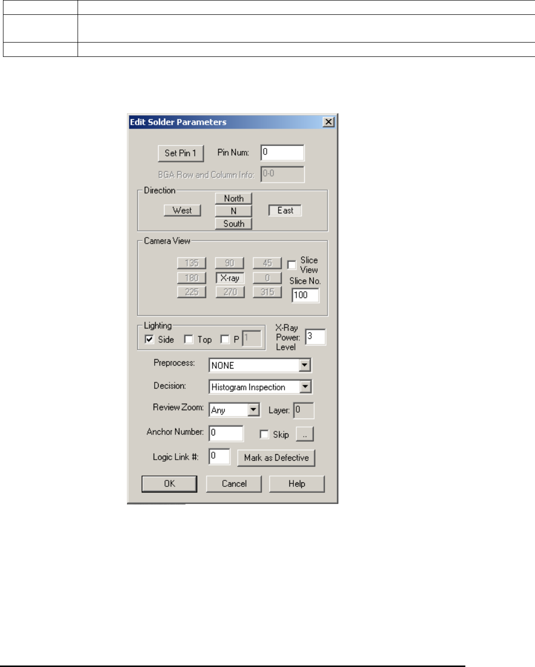
10.4.1 Edit Solder Parameters
Select Edit Solder Params.. from the Solder pop-up menu to open the Edit Solder Parameters
dialog.
The Pin Number box defines the solder box’s pin number.
Press the Set Pin 1 button to set the pin numbers for all solder boxes using a counterclockwise
convention.
The rest of the buttons on the dialog set the Direction, Camera View, Slice View, Slice No. and
Lighting for the inspection. You can also select one preprocess and one decision algorithm for
the inspection.
10-24 General Inspection Methodology
Currently there are seven decision algorithms for the solder inspection box: Histogram
Inspection, Pattern Matching, BGA Analysis, BGA Pin Inspection, Solder Blob Analysis,
Percent Void Inspection, PTH Solder Analysis, Fusion Solder and Xray Solder Analysis.
BGA Analysis and BGA Pin Inspection are for BGA solder. See 10.5.3 Solder Inspection for
more details. Fusion Solder is for the M1 AOI System with RGB light. Solder Blob Analysis and
PTH Solder Analysis are through-hole inspection algorithms for Nordson YESTECH AOI
systems only. Fusion Solder and PTH Solder Analysis are not used for X-ray inspection. Percent
Void Inspection is for void detection of solder joints under X-ray. Xray Solder Analysis is for
Resistor solder under X-Ray inspection.
All solder inspection boxes can be anchored by a marking box. Refer to 14.4 Anchor Block
Fiducial and Local Fiducial on the functionality of anchors. The X-ray Power Level specifies
the current X-ray power level used for current solder inspection. The Skip checkbox records
whether to skip (don’t inspect) current solder or not.
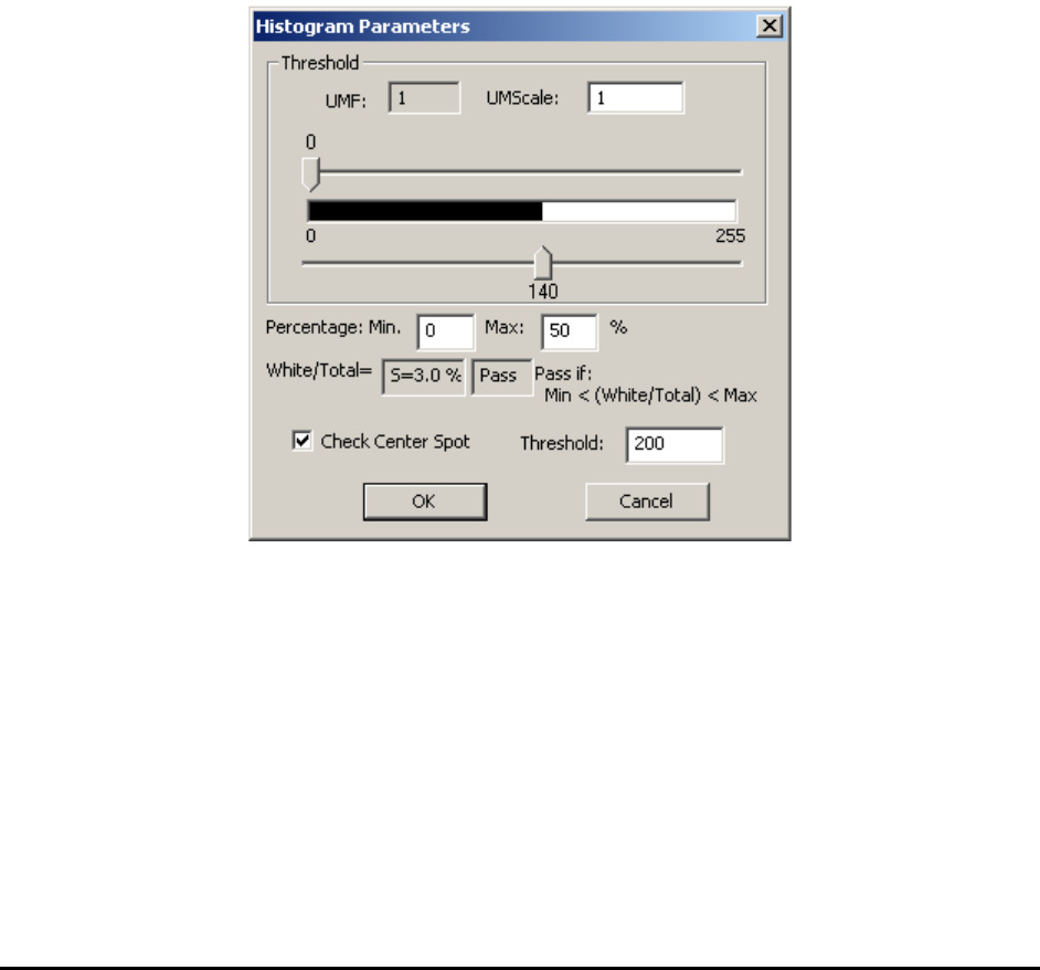
10.4.2 Histogram Parameters
Select Histogram Setup from the Solder pop-up menu to open the Histogram Parameters dialog.
Histogram inspection uses two threshold values to binarize the image into black or white pixels.
The algorithm then makes a decision based on the ratio between the two. The UMF and
UMScale are used for uniformity compensation which is disabled by default.
In X-ray view, histogram inspection can effectively detect insufficient or excess solder defects.
General Inspection Methodology 10-25
The Check Center Spot is for AOI inspection and should not be enabled for X-Ray inspection.
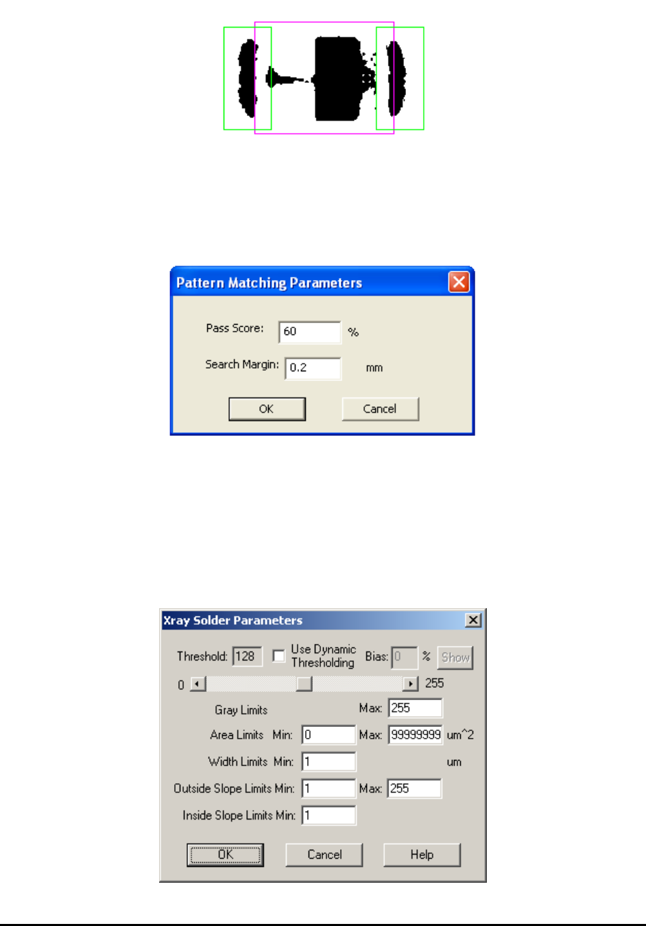
10.4.3 Pattern Matching Parameters
Select Pat Match Param.. from the Solder pop-up menu to open the Pattern Matching
Parameters dialog.
Pattern matching is more commonly used in Mark inspection, but can also be used in solder
inspection. The idea is to use a known “good” solder joint as a template to check the others
against. During inspection the image of every joint is compared to the template and joint images
(defined by the pass score) are rejected.
10.4.4 X-Ray Solder Parameters
Select X-ray Solder Setup from the Solder pop-up menu to open the Xray Solder Parameters
dialog.