YesAX V3.1.2 - Software User Manual.pdf - 第143页
General Inspecti on Methodolo gy 10 - 49 7. Check the BGA group parameters and make sure the binar y thre shold works for current slice. The binary threshold of the BGA group a lgorithm for 3D slices and 2D images are no…
10-48 General Inspection Methodology
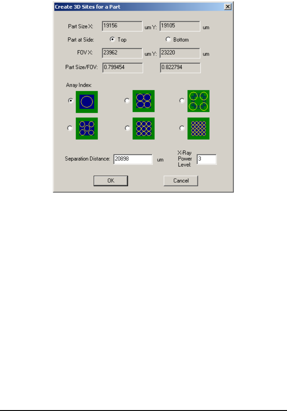
There are six different layouts to choose from. Each layout provides a solution of
different number and location of 3D sites. User may select either one of them. There is
one default separation parameter for each layout, which indicate how much off those 3D
sites are from the center of the package. User can either use the default parameters or
type in a different number. Once OK button’s been presses, the corresponding future 3D
sites will be added to the recipe and to the map view window automatically.
3. Unless the board being inspected is very flat, always allocate laser reference sites for
these 3D sites and run height profile. After height profile’s been created, the height map
of all 3D sites will become available for inspection.
4. For BGA mounted on top side of the board, set middle layer to slice number 0 first and
then adjust surface offset, make sure to get the largest ball size as possible. During initial
training it is preferable to use a good BGA sample (the largest ball diameter appears the
middle layer of the ball).
5. Measure the ball diameter and get ready to add the BGA package slice and pad slice to
the 3D site and the BGA package. Since BGA balls normally collapse after reflow. It is
preferable to pick the slice which is about 70% to 80% of ball diameter away from the
middle slice. For example, if the maximum ball diameter is 36pixel under 1” FOV, we
may want to use slice number -15 and 15 for package slice and pad slice, respectively.
6. Set slice number to 0 and then use the “IB to current slice” function and convert all
inspection boxes from 2D view to 3D slice view with slice number 0. It is a good idea to
have the name of the package and part ready so we can update the package and part
library.

General Inspection Methodology 10-49
7. Check the BGA group parameters and make sure the binary threshold works for current
slice. The binary threshold of the BGA group algorithm for 3D slices and 2D images are
not always the same.
8. Switch to slice -15, use copy “IB to current slice” function and create all inspection boxes
for slice -15. For BGA group algorithms, since the ball size is smaller, we normally apply
15% (sometimes 12%) for the ball size check. The binary threshold will also be different
and needs to be re-adjusted. For BGA pin inspection algorithm, it is important to the ball
diameter for slice 0 and slice -15 to different number. After slice -15 is done, do the same
thing for slice 15. Normally ball sizes for slice 15 and -15 will be about the same, which
leads to similar parameter values for these two slices. Remember to update package and
part library at the end. This way a new package for 3D BGA inspection is created.
9. For BGA mounted on bottom side, depends on the board thickness the middle layer is
normally set to a negative number, and the other two slices are set accordingly. For
example, if the board thickness is 60 mil and the BGA package is programmed under 1”
FOV, we may set the middle slice of the BGA to be slice number -60, and the other two
slices to -45 and -75, respectively.