YesAX V3.1.2 - Software User Manual.pdf - 第45页
User Interface B asics 4-9 4.7 Status View The status view displays various status information related to the inspection process as well as the disk space. Optionally you can open a second status window. Right click on t…
4-8 User Interface Basics
Select which side part bodies (in purple box) should be
displayed on screen. The default is showing both side parts on
screen. The user can also choose to display only top side parts
or bottom side parts. This option is mainly used during recipe
programming period. In case there are two parts, one on top and
one on bottom, that exactly overlap with each other, it is
preferable to display one part at a time and avoid possible
confusion. Whether the part is on top or bottom is specified by
“Is Bottom Side Part” option inside Edit Part Parameters dialog.
NOTE
that this concept is different from that of
top/bottom side part list. There should be only
one top side part list throughout the program, and
no bottom side part list.
Camera view selection. From the left to the right X-Ray view
and top vision view.
Select Capture mode.
Select Live mode.
Train new part manually without CAD data.
Toggle side light on or off.
Toggle top light on or off.
Run Inspection.
Inspect Current Screen
These 4 buttons enable or disable the display of the region or
interest boxes on the overlay. From left to right they
enable/disable marking boxes, solder boxes, lead bank boxes
and part body boxes.
Move to home position.
Perform fiducial alignment.
Move the XY stage and camera assembly away from the board
area. Provides access to the board using the front door.
Stop all motion and process.
Feed board on the conveyor.
Put annotation, annotation marker and annotation stamp on
current X-ray image.
Apply 3D Rendering on current X-ray image.
Activate on-line help feature.
X-ray Field of View (FOV) selection. X2 has 1”, 0.5” and 0.25”
FOV while X3 only has 1” and 0.5” FOV.
User Interface Basics 4-9
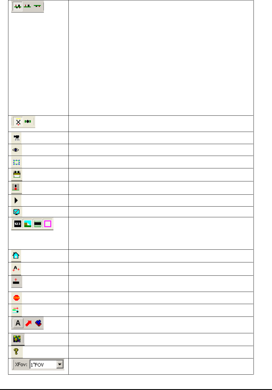
4.7 Status View
The status view displays various status information related to the inspection process as well as
the disk space.
Optionally you can open a second status window. Right click on the Status 1 dialog to open the
Status 1 pop-up menu and select Show Status2 View. The second status window displays status
information for a FIFO (First-In-First-Out) buffer used during downstream review.
4.8 X-ray Control Bar
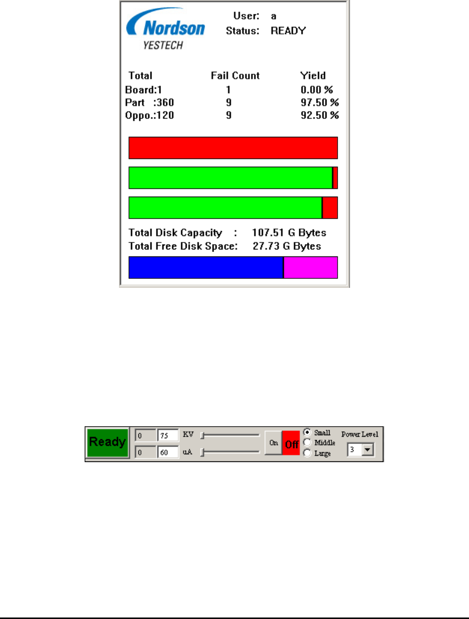
The X-ray control bar displays various status information and controls for the X-ray tube. With
the X-ray Control, the user can interactively control and monitor the X-ray source from the
YesAX software, instead of using the control panel of the X-ray source. When the YesAX is
started, the X-ray Control Bar dialog appears at the upper right corner of the screen.
The X-ray Control Bar displays the current status of the X-ray source, its voltage and current
levels. It is also able to continuously update the information in real time.
Use the On and Off buttons to turn on and off the X-ray. When the X-ray is on, the control bar
shows “X-ray On” inside its status pane, and also continuously displays and updates the voltage
and current levels.
The two left boxes display the preset voltage and current. To change the demand voltage or
demand current, use the two sliders next to the voltage and current fields.

4-10 User Interface Basics
To change the X-ray focal spot size, select one of the options on the right: Small, Middle or
Large. Smaller spot sizes generate an image with better resolution.
NOTE If the spot size is changed while the X-ray is on, X-ray will be turned off
automatically. Touch the X-ray On button to turn the X-ray back on.
Since the X-ray tube used on the X3 AXI system only has one spot size available, there is no
spot size selection area available for X3 AXI system.
The position of the control bar can be changed. To do that, left mouse click on the control bar,
drag it to a new position, then release the mouse button.
For each X2/X3 AXI system there are ten pre-defined X-ray power level settings. Each power
level has its own voltage, current and spot size settings. During system calibration values of
voltages and currents of each power level will be adjusted so that for the same kind of sample,
the same power level of different systems will generate very similar levels of image quality. To
use a pre-defined power level, select the specific power level from the drop down list and then
click the X-ray On button.
4.9 3D Control Dialog
The 3D Control dialog displays various status information and control for 3D related inspections
and operations. This dialog box is designed for X3 AXI systems only. Details of 3D inspection
will be described in Section 10.