YesAX V3.1.2 - Software User Manual.pdf - 第106页
10 - 12 General Inspecti on Methodolo gy Lead bands can be anchored by a marking for precise positioning. See 14.4 Anchor Block Fiducial and Local Fiducial for details. The X-ray Power Level specifies the current power l…
General Inspection Methodology 10-11
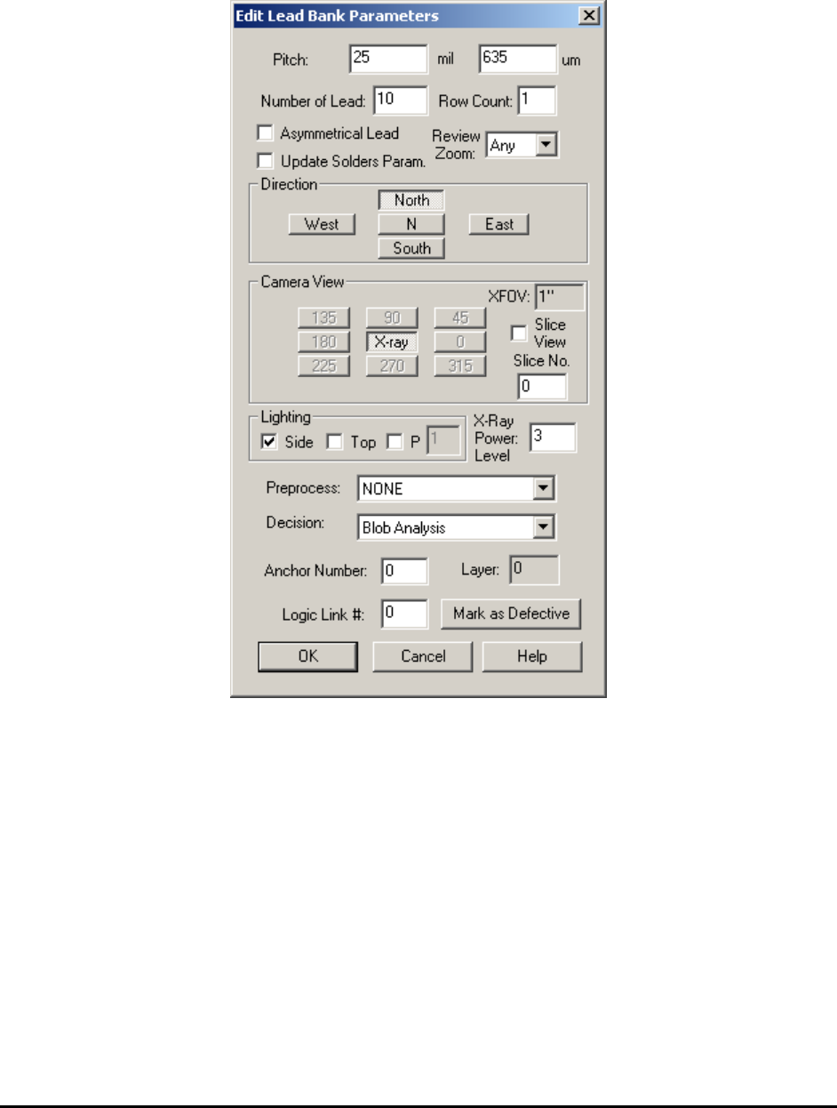
10.3.1 Edit Lead Bank Parameters
Select Edit Lead Bank Params.. from the Lead Bank pop-up menu to open the Edit Lead Bank
Parameters dialog.
Set the pitch of the lead, the number of leads in the lead bank, the direction, the view, the
lighting and the algorithm selection.
The Asymmetrical Lead checkbox should be checked if the lead arrangement for the part is not
symmetrical. For example on SOT-25 parts there are two leads on one side but three on the
opposite.
The Update Solders Param. Checkbox will allow the same settings (Direction, XFOV, Lighting
and XPL) which the current lead bank uses apply to all solders within the lead bank, if checked
by user.
The Row Count should always be 1 for all the normal components. Multiple rows of leads per
side is for pin array inspection or BGA solder ball or solder paste inspection only.
The Review Zoom list box selects the preferred zoom level for reviewing this lead area during
the defect review process.
10-12 General Inspection Methodology
Lead bands can be anchored by a marking for precise positioning. See 14.4 Anchor Block
Fiducial and Local Fiducial for details.
The X-ray Power Level specifies the current power level for lead inspection.
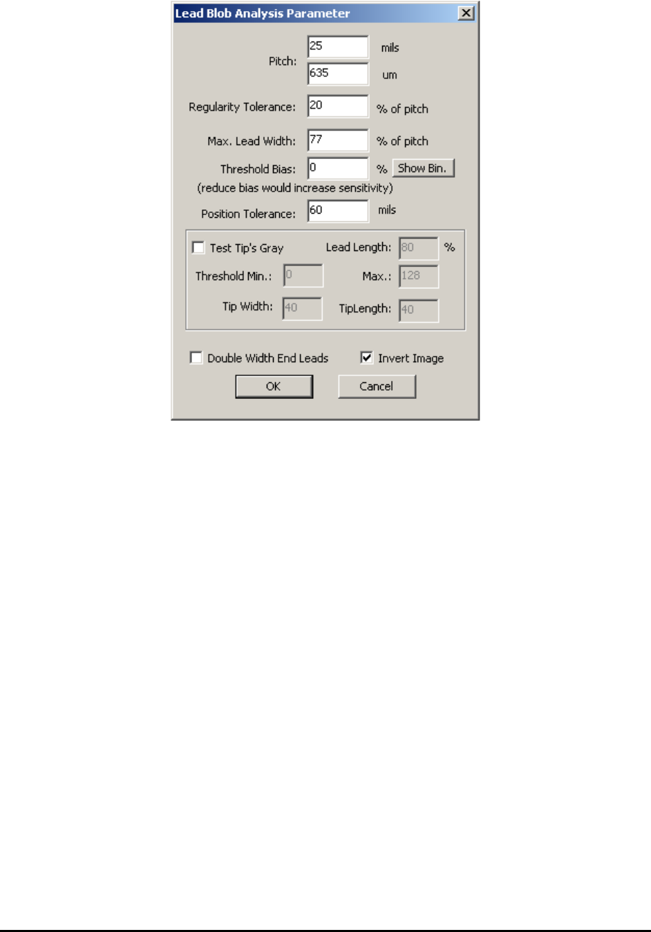
10.3.2 Lead Blob Analysis Parameter
Select Lead Bank Parameters from the Lead Bank pop-up menu to open the Lead Lob Analysis
Parameters dialog.
General Inspection Methodology 10-13
Pitch is the separation from one lead to the next. It can be in mils or microns. (Typical values are
20 mils, 25 mils, 50 mils)
Regularity Tolerance means the lead to lead separations are the same from lead to lead. Set this
tolerance to detect bent leads or missing leads. A value of 10% is typical for this parameter. It
can range from 5 to 50%.
Max. Lead Width defines the maximum apparent width of a lead. Set this parameter to detect
bridging or lead off pad conditions. A value of 65% is typical for this parameter. It can range
from 50 to 95%.
Threshold Bias can be used to increase or decrease the inspection sensitivity. Reducing the
Threshold Bias e.g. – 10% will increase the sensitivity of the detection. The Show Bin button
displays the binarized image.
Position Tolerance checks for lead position shift.
Test Tip’s Gray checks the brightness level on the tip of the lead pad to detect for lifted pin
defect conditions. Normally a lead solder is wetted up to the lead’s heal and toe so there should
be little or no solder on the tip of the pad. Amble solder on the tip of the pad indicates a lifted
condition.
On some board layouts the end pad is made twice the width of the other lead pad. The Double
Width End Leads checkbox informs the software of such layout.
Invert Image checkbox will invert the pixel value of the image before performing the analysis.