YesAX V3.1.2 - Software User Manual.pdf - 第109页
General Inspecti on Methodolo gy 10 - 15 When reviewing a defect that is on the edge of a long lead bank, depending on the viewing zoom level, the defect could be outside the video view window. Breaking the lead bank int…
10-14 General Inspection Methodology
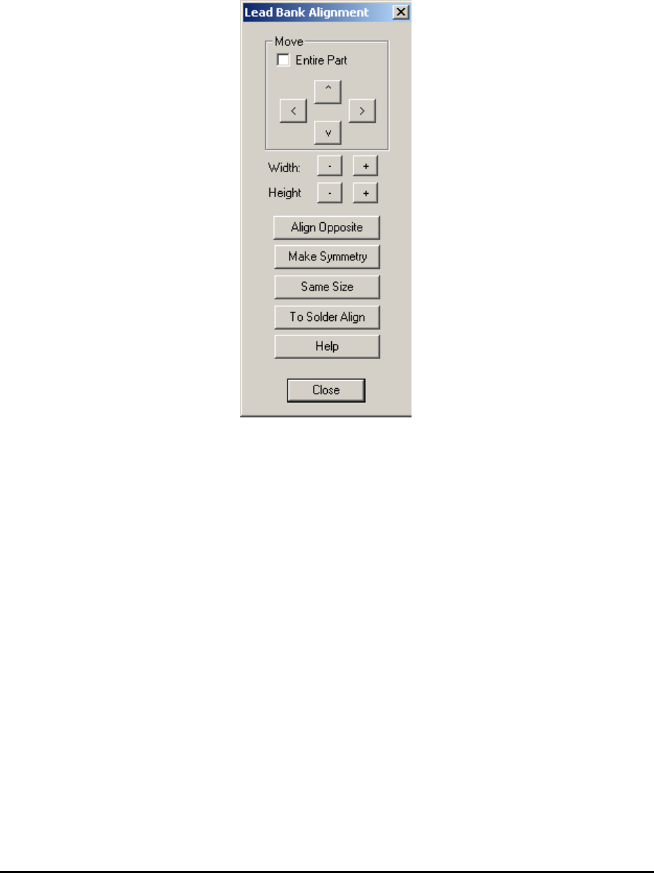
10.3.3 Lead Bank Alignment
Select Align.. from the Lead Bank pop-up menu to open the Lead Bank Alignment dialog.
Use this dialog to move and size the Lead Inspection box.
The Align Opposite button aligns or create the lead inspection on the opposite side of the part.
The Make Symmetry button moves the lead box so that it is symmetrical with respect to the
centroid of the part.
The Same Size button makes all the lead boxes the same size.
The To Solder Align button brings user from Lead Bank Alignment dialog box to Solder
Alignment dialog box with one click.
The Help button launches the help topic about this dialog.
10.3.4 Break Lead Bank into Sectors
Select Break into sectors.. from the Lead Bank pop-up menu to open the Break Lead Bank into
Sectors dialog.
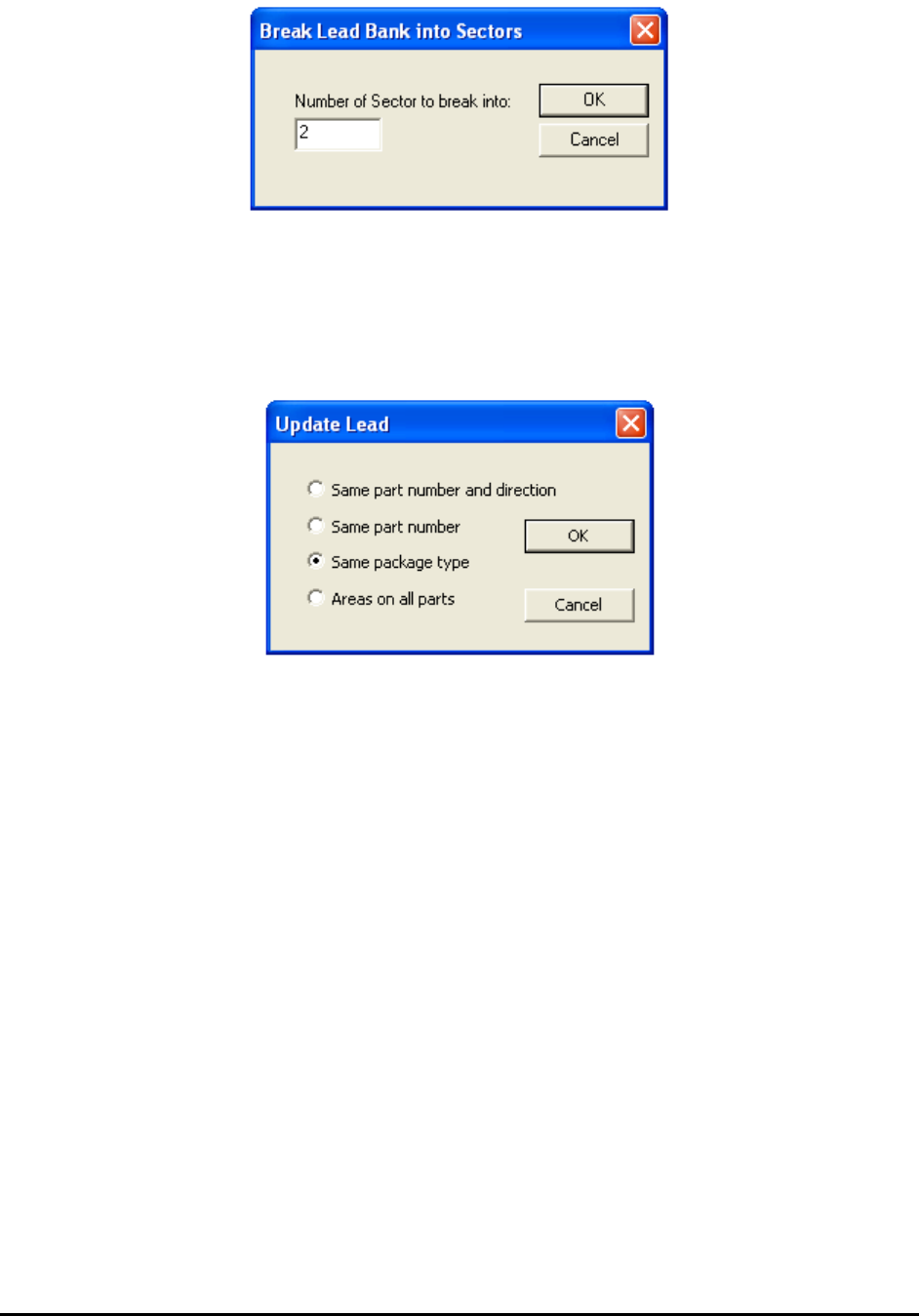
General Inspection Methodology 10-15
When reviewing a defect that is on the edge of a long lead bank, depending on the viewing zoom
level, the defect could be outside the video view window. Breaking the lead bank into smaller
sectors ensures the lead defect be shown on the screen during review.
10.3.5 Update Lead
Select Update from the Lead Bank pop-up menu to open the Update Lead dialog.
10.3.6 Bond Wire Params..
The Bond Wire Sweep algorithm is exclusively designed for bond wire components. It can detect
wire bond locations, bond wire exit angles and bond wire displacement. To use this algorithm,
the Bond Wire Sweep needs to be selected as decision algorithm inside the Edit Lead Bank
Parameters dialog. Also the number of lead needs to be set to 1. After that select the Bond Wire
Params.. menu item inside lead bank popup menu will launch the following dialog.
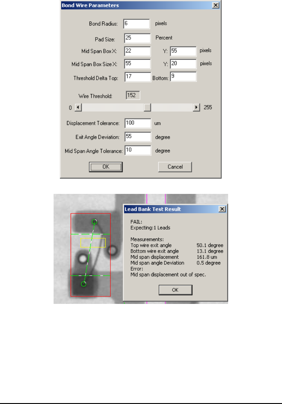
10-16 General Inspection Methodology
The result dialog and the inspection screenshot are shown below:
The Bond Radius field is used to specify the size of wire bond joints attached to the die. By
default the bond wire will attach to die at two different locations. These two are at the opposite
of the inspection box and suppose to be the darkest areas inside the whole lead box. During
inspection the first step is to locate the attached positions. If any joint cannot be detected the
inspection will fail automatically.