YesAX V3.1.2 - Software User Manual.pdf - 第14页
1-2 Introduction 1.1.1 System Block Diag ram for X 2 AXI S ystem XY Stage A lignment Camera A ssembly Top Light A ssembly Side Light Asse mbly Conveyor EBOX 1 I/O Control EBOX 2 Servo Motor Control PC LCD Monitor Key boa…
Introduction 1-1
1 - Introduction
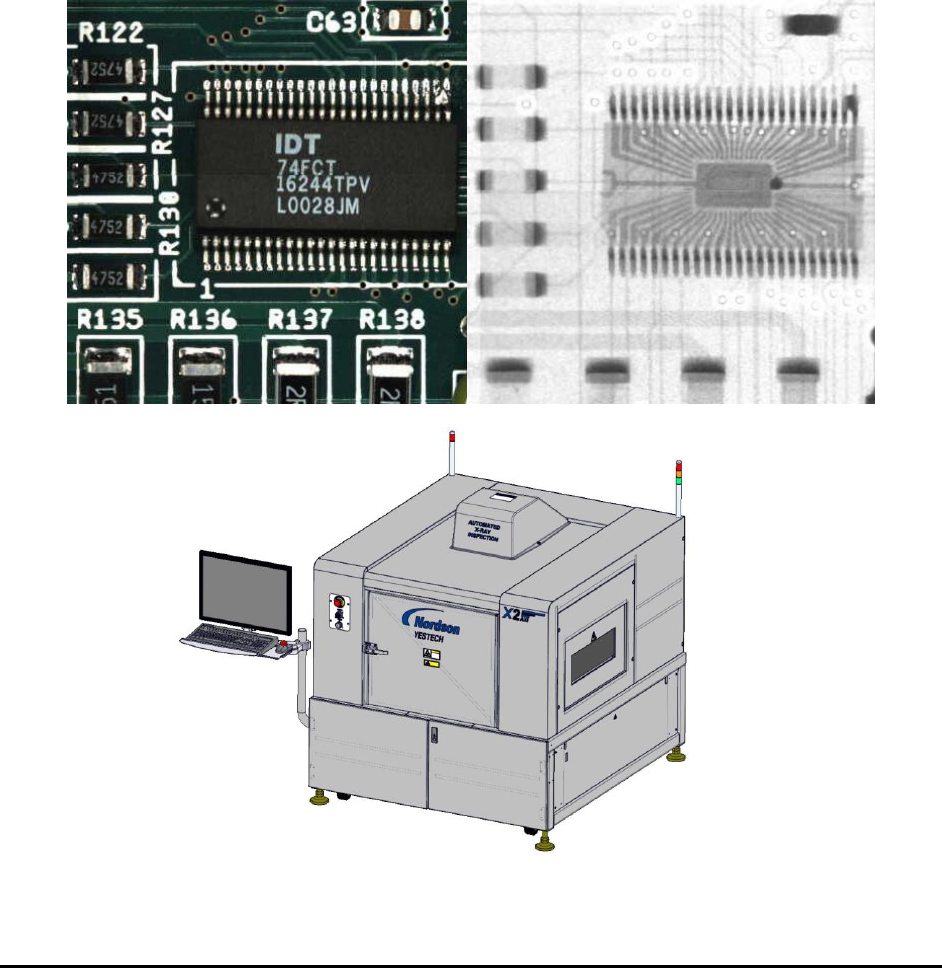
YESTech Automated X-Ray Inspection (AXI) is an effective technology for finding
manufacturing defects in electronic assemblies.
1.1 Automated 2D Inspection System –X2
Nordson YESTECH’s X2 AXI System is a fully automated 2D X-Ray inspection system. It can
couple with an AOI machine to perform dual technology inspection. The X2 AXI System is
equipped with an X-Ray camera as well as a vision camera. The vision camera is mainly used for
generating background map image for the board being inspected. It can also be used to read
barcodes from the boards. Other than that, all inspection functions are performed under X-Ray
camera view and by X-Ray inspection methodologies.
1-2 Introduction
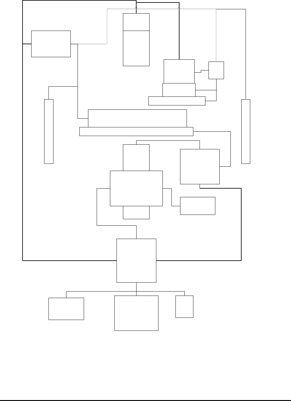
1.1.1 System Block Diagram for X2 AXI System
XY Stage
Alignment
Camera
Assembly
Top Light
Assembly
Side Light Assembly
Conveyor
EBOX 1
I/O Control
EBOX 2
Servo Motor
Control
PC
LCD
Monitor
Keyboard
Mouse
IEEE 1284
LCB
X-ray
Intensifier
X-ray
Camera
Z
Stage
X-ray Tube
X-ray Power
Supply
Left Shutter
Right Shutter
RS232
USB2
USB2
USB2
Introduction 1-3
1.2 Automated 3D Inspection System –X3
Nordson YESTECH’s X3 AXI System is a fully automated 3D X-Ray inspection system. The
X3 system is like an X2 - 2D machine but with extra 3D inspection capabilities. In other words,
the X3 can not only do a full 2D inspection of a PCB as X2 does, it can also do a 3D inspection
of the PCB. During inspection the 2D and 3D inspections are optimally combined together to
achieve both speed and capability requirement.
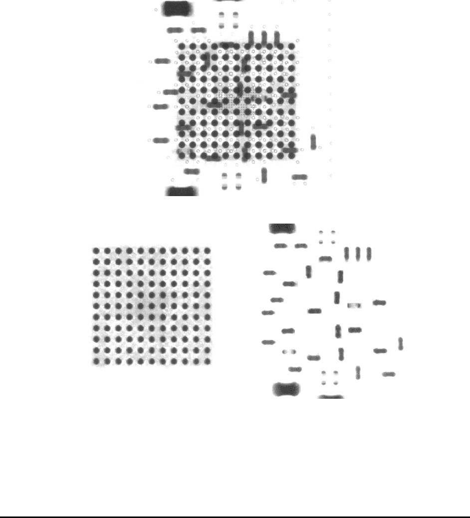
In practice the X3 “ looks” at the solder joint from 8 (or more) different angles and then, by
combining the captured image set using digital tomosynthesis reconstruction algorithms, creates
slices parallel to the board surface. These slices can separate the top side from the bottom side so
that each side of the double sided board can be independently analyzed.
2D X-ray Image
3D Top Slice 3D Bottom Slice
The height offset of the board’s top surface can be measured by using a laser device and this
information is used to compensate for board warp. It is possible to setup the parameters and the
position where the laser measurements will have to be made and the range over which the
measurement will be effective.