YesAX V3.1.2 - Software User Manual.pdf - 第154页
11 - 10 3D X-Ray Inspection Methodolo gy To add a laser height reference to recipe, the vision view must be selected first. When adding a new part, make sure the Ref ID c ontains string “S100_REF”. The format of laser re…

3D X-Ray Inspection Methodology 11-9
Power Level indicates the power level setting used by current 3D site. It is possible to change
the power level. To do this, please turn on X-ray first and pick a different power level, when X-
ray power is stabilized pressing the Update button underneath will allow software to update the
power level of 3D site to current number. Please remember to re-capture the site once power
level’s been modified. Also if inspection boxes have been created inside the current 3D site, it is
possible to check power level settings of those inspection boxes and make sure the numbers
match with 3D site’s power level settings.
Pitch and Roll indicate how much the current surface is tilted in the x and y direction. The
perfect flat surface will have both pitch and roll values set to 0. Bigger number of pitch and/or
roll indicates the board tilts a lot in current location. If there is no laser reference or only one
laser reference within the range of the 3D site, the pitch and roll will also be set to 0.
The Surface Height, Pitch and Roll information are all obtained from the laser surface map. Once
the number of slices has been added to the list, the only parameter the user needs to adjust is the
surface offset. For the same board, if all the inspection boxes are either on the top surface or
bottom surface, the site offset numbers should be very similar between different 3D sites. For
BGA inspection, since the middle ball slice is not on either surface, the surface offset value for
3D sites that contain a BGA package will be different from other 3D sites. The slider bar and site
offset adjustment when moving up and down will show slice in different z level in real time. But
if the Pitch and Roll are not both set to 0, the user still needs to click the Apply button to see the
real slice which reflects the height change.
The inspection area on a slice is affected by the FOV size, the overlap setting in the Extended
Recipe Option page and its slice number. Slices farther away from the reference height (Slice
Number = 0) has a smaller inspection area. The Ext. Ispn Area (Extended Inspection Area)
checkbox if checked extends the inspection area for all slices of the site to that of the reference
height slice (Slice Number = 0).
Once a site has been added the user can start placing parts/inspect boxes on certain slice level of
3D site and finish the rest of 3D programming. This part of programming will be similar to the
normal 2D programming.
11.5 Laser Height Measurement
Laser height measurement is very useful for 3D inspection, especially in the situation that the
surface of the board is not flat or the board warps a lot. Please note that the Laser height
measurement is actually performed by a vision camera.
11-10 3D X-Ray Inspection Methodology
To add a laser height reference to recipe, the vision view must be selected first. When adding a
new part, make sure the Ref ID contains string “S100_REF”. The format of laser references is
like “S100_REF_N” while N is the ID of current laser reference. For example, a laser reference
with name “S100_REF_10” will have the ID of 10. When allocating laser references
automatically by using method mentioned in next sector, system will assign names to each
reference automatically, with the ID in a one-by-one increment order. When placing the
reference, under Vision View, select a clean spot which is not close to any via holes or shining
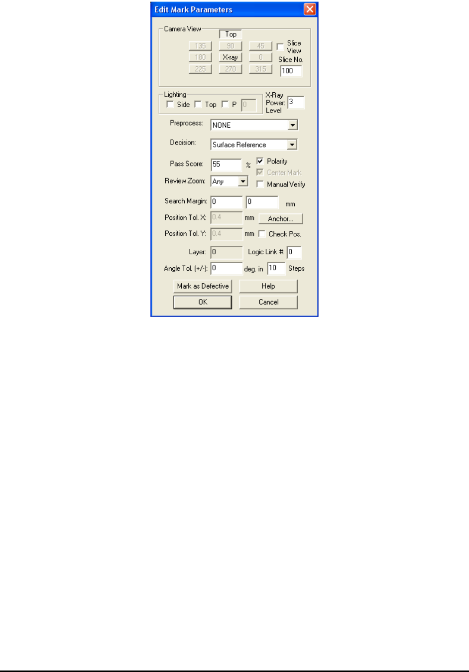
components. This spot must be close to the 3D site. The laser height measurement is a mark
inspection. When launch the Mark Parameter dialog, please make sure no Lighting is selected
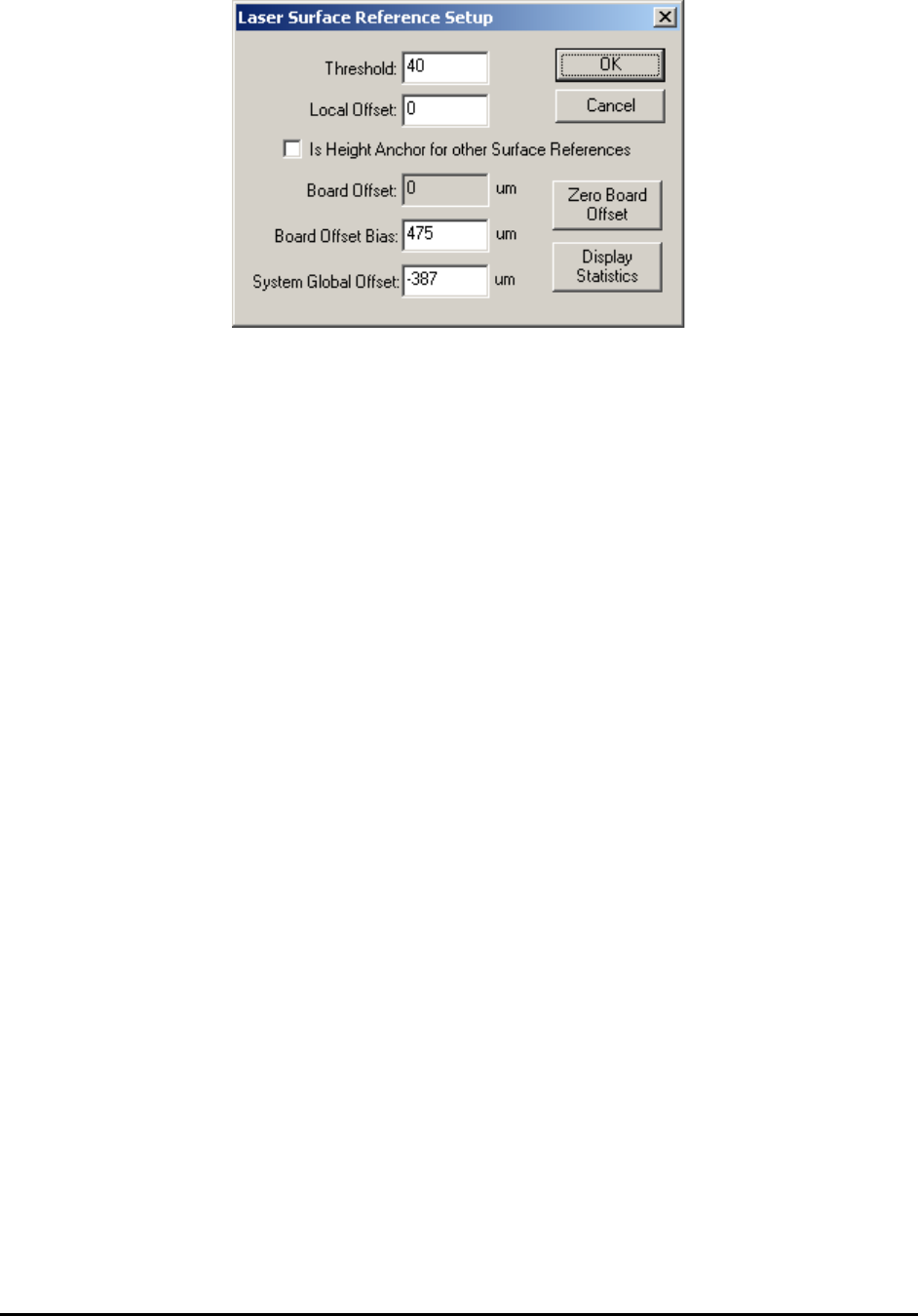
and the decision is set to Surface Reference. The Laser Surface Reference Setup dialog is show
below.
3D X-Ray Inspection Methodology 11-11
Threshold is the binary threshold that binarizes the laser spot image. A larger threshold number
will produce a smaller laser spot blob. The center of laser spot blob will be measured and used
for the rest of the calculation.
Local Offset is used to compensate the height of current laser surface reference point. By default
this parameter is set to 0. In cases like user wants to put laser on top of a surface other than the
normal board surface, i.e., top surface of component on board, a different layer on board surface,
but still want to use the current height measurement to represent the height of board surface, if
the height difference between another layer and board surface is known, it can be typed in Local
Offset field and allow the algorithm to offset the measurement result automatically. The unit of
this measurement is um.
Is Height Anchor for other Surface References is turned off by default. When programming a
3D recipe, the user needs to allocate two laser surface reference locations which are very close to
board front edge or back edge and close to each other. These two laser references will be served
as height anchor for the whole board. Do several tests on each reference points and get the
average height of these two points. Then open the Laser Surface Reference Setup dialog, click to
enable the “Is Height Anchor for other Surface References” option and type the average height in
the Board Offset Bias field.
Board Offset displays the average height of height anchor points. If there is no height anchor
points defined in current recipe, the board offset will always be 0.
Board Offset Bias store the negative number of original board offset during recipe program fine
tune. For example, if the average height of two height anchor points is around 550um, then the
board offset bias should be set to -550. This number is saved per recipe. After board offset bias’
been set, if user click Zero Board Offset button first then do a test on laser reference with its
height anchor selection turned on, the test result should be around 1100um. Once user launches
the 3D control menu (which will be discussed in next section) and clicks the Profile Board
Height command to run the test for all laser height references, the board offset will be calculated
automatically. In this case the board offset will be 550um. After that if user runs a test on height
anchor points, the result will go back to around 550um. Once the system finishes inspection for
one board, the calculated board offset number will be saved to the log file “SurfaceRef.log”,
which is under current recipe folder, automatically.
System Global Offset was set by manufacturer during system calibration. This was designed for
early version YTX-X3 system only and should leave as 0 for most systems.