YesAX V3.1.2 - Software User Manual.pdf - 第159页
3D X-Ray Inspection Methodology 11 - 15 Other than the blue boxes representing the inspection box and white circle indicating the location of 3D sites, there will be extra yellow lines c onnecting center of 3D sites and …
11-14 3D X-Ray Inspection Methodology
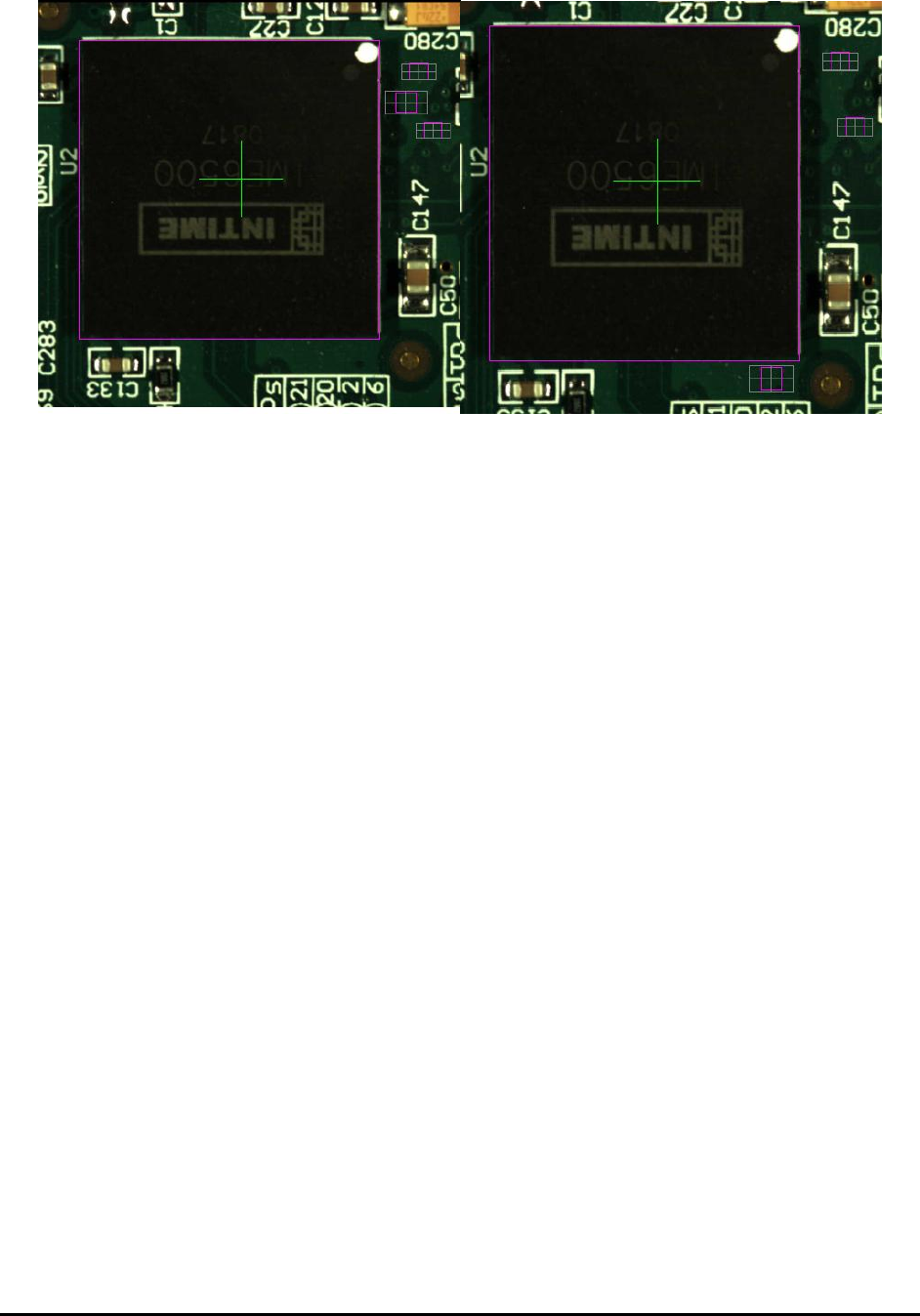
During 3D programming it is important to allocate at least three height reference points per 3D
site and make sure each 3D site has the best height reference locations available. YesAX
software has provided user an easy way to tell what height references were used by the current
3D. First, user needs to make sure to run Profile Board Height command once or run the
inspection once to create/refresh the height map. After that if user saves the recipe the latest
reference height information will be saved to ZMap.txt file which is under current recipe folder.
If user only runs Profile Board Height command once, the next thing he needs to do is to switch
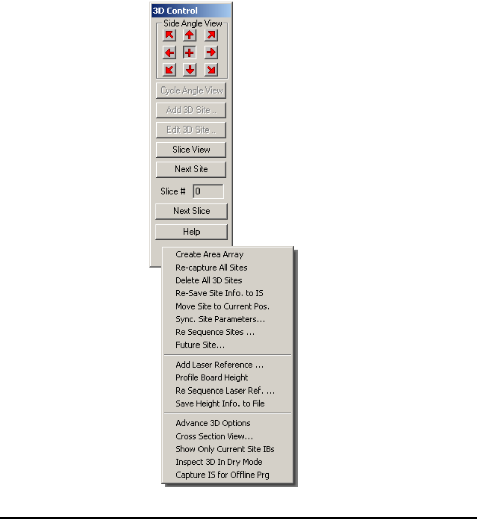
to 3D mode, go to first 3D site and then use the >> navigation button inside the 3D control
window and go through the rest of the 3D sites. If user doesn’t want to go through every 3D site,
it is possible for him to only go through those 3D sites which he’s interested. After that all he
needs to do is to maximize the map view window. The window will show extra information
other than the normal blue boxes. Below is a screenshot of part of the window:
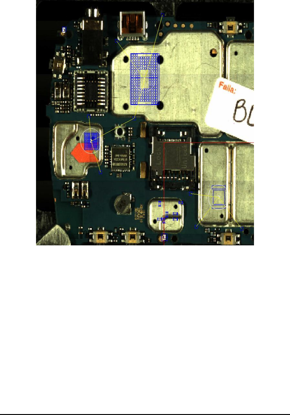
3D X-Ray Inspection Methodology 11-15
Other than the blue boxes representing the inspection box and white circle indicating the location
of 3D sites, there will be extra yellow lines connecting center of 3D sites and height references
they’ve been using. By looking at this picture user would be able to check which height
references were being used by which 3D sites. Since the locations of height references are
important for constructing height map of 3D sites, it is advisable for user to check every site
carefully and make sure all 3D sites uses height references in best locations as possible. Once
restore the map view window to its normal size, the background map will be refreshed again and
the yellow lines will disappear.
In situations that certain 3D site doesn’t have the best height references, the user can do the
following: 1. Move the current height reference points to a better location. 2. Add more height
reference points to the recipe. Once user modifies the location of any height reference points,
they need to go through all 3D sites again and then maximize the map view window to see the
updated results.
If the results are still not the best and it seems too difficult to move existing height references
around, one other option available is the force reference function. User needs to go to the 3D site
and launch the Edit 3D Site dialog.
11-16 3D X-Ray Inspection Methodology
Clicking the Height Ref. button will launch the Slice’s Height Reference dialog and the user can
type in the force reference ID in the field. Up to two force references can be added for each 3D
site. When finish all the changes the user still needs to go through all 3D sites’ been modified
and then maximize the map view window to see the updated map. Software will always include
the force references inside the list and pick two or one other height references which are nearest
to the center of current 3D site for height map construction purpose.
11.6 3D Inspection Pop-up Menu
Right click on the open area of the 3D control window will launch the advance 3D site
management menu. All items in this menu are either belongs to 3D site management or other
related operations.