YesAX V3.1.2 - Software User Manual.pdf - 第31页
Unpacking and Installation 3-1 3 - Unp acking and Inst allation Nordson YESTECH typically sends field service engineers to install the X2 / X3 AXI Sy stems and to provide training to the new customers. However, it is not…
Safety 2-11
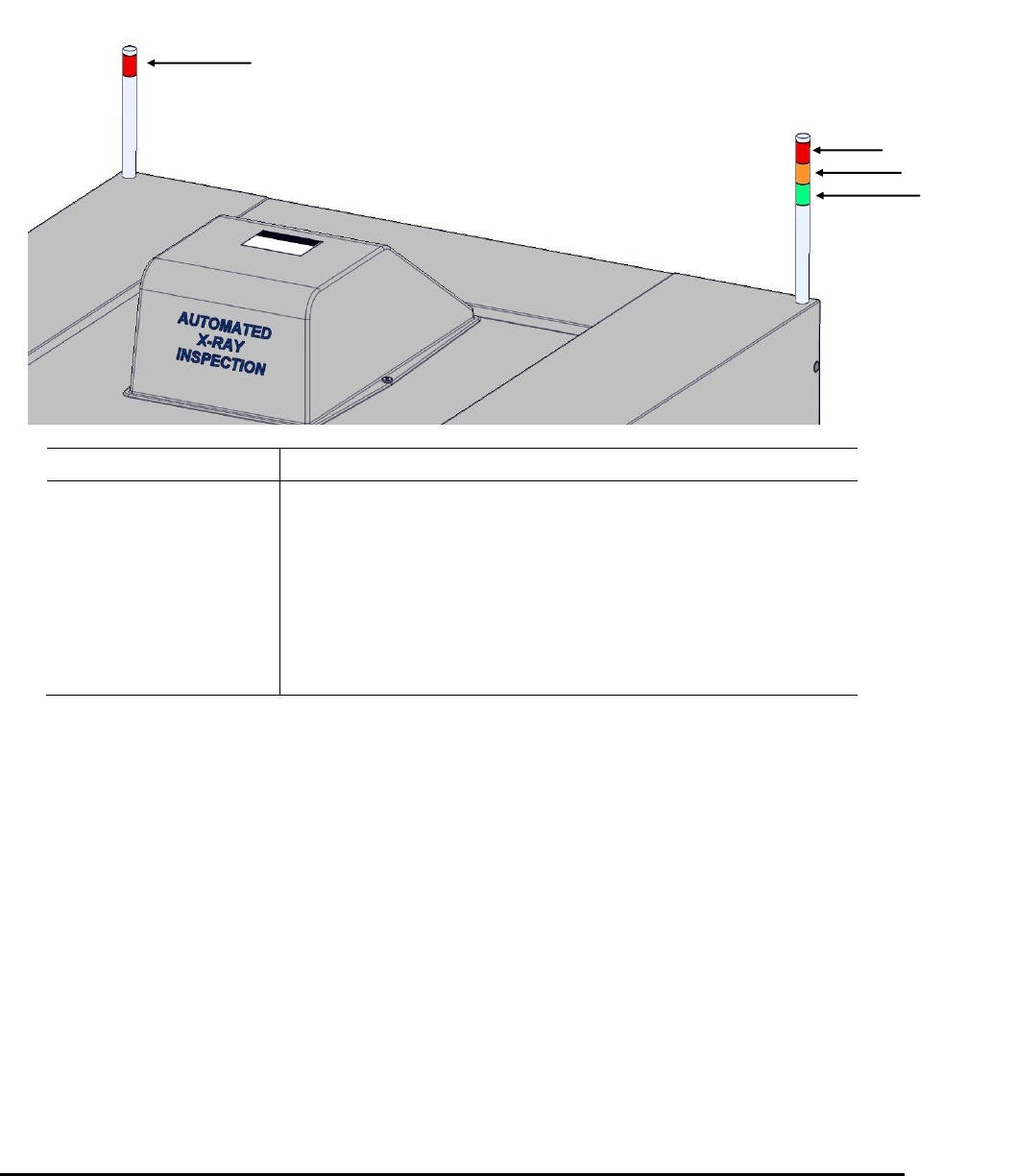
2.12 Light Tower Status Lights
The AXI systems include a PLC-controlled light tower (Figure 2-5) that constantly shows the status of the
current operation.
Light Color
System Status
RED – LEFT
The X-Ray is ON.
RED – RIGHT
A system error is present. Refer to Section 23 - Customer
Support for recovery information.
YELLOW
The system is idle.
GREEN
The system is in operation and processing material.
GREEN and YELLOW
The system is in start mode and waiting to successfully process
the first substrate.
Figure 2-5 Light Tower Status Lights
RED
YELLOW
GREEN
RED
Unpacking and Installation 3-1
3 - Unpacking and Installation
Nordson YESTECH typically sends field service engineers to install the X2 / X3 AXI Systems and
to provide training to the new customers. However, it is not difficult to install and tune a newly
arrived X2/X3 AXI system. This section describes the steps.
3.1 Safety First
Operation of your X2/X3 AXI System involves, air pressure, electrical power, and mechanical
devices. It is essential that every person servicing or operating the X2/X3 AXI System fully
understands all hazards, risks, and safety precautions. Refer to Section 2 - Safety for additional
information.
WARNING! CAUTION!
To ensure optimal performance and safety, it is necessary to install the X2/X3 AXI
System in a facility that meets the necessary requirements listed in Section 29 -
Specifications.
If you have any questions, please contact Nordson YESTECH Technical Support.
3.2 Facility Requirements
To ensure optimal performance and safety, it is necessary to install the X2/X3 AXI System in a
facility that meets the requirements. If you have any questions about facility requirements, please
contact Nordson YESTECH Technical Support. See 29.2 Facility Requirements for detailed
information.
WARNING! CAUTION!
Make sure that your facility meets all requirements listed in 26.2 – Facility
Requirements. Failure to meet these requirements could result in serious bodily
injury to personnel and damage to the AXI system.
3.3 Unpack
After unloading the machine from the truck, remove all the packaging material. Use a power
fork-lift to lift the machine off the wooden pallet. The X2/X3 AXI System weighs about 5000 lbs.
The best place to insert the fork is from the back of the machine under the base frame.
All X2/X3 AXI System have castors allowing them to be wheeled around by 2 to 4 people once on
level ground. After moving the machine to the desired position, lower its four leveling pads so
that they lift the wheels up and support the entire weight of the system.
3.4 Remove Shipping Bracket
There is a red colored shipping bracket that holds the XY stage in place for shipping. It must be
removed before operation.
3-2 Unpacking and Installation
3.5 Install the LCD Monitor
To prevent damage during shipment, the LCD monitor is removed from the machine and shipped
in its own protective package. When the X2/X3 AXI System leaves the factory, the monitor arm
assembly is attached to the left side of the machine. However, the monitor arm assembly can be
attached to either the left or the right side of the machine. During installation you would decide
which side would be the most appropriate for attaching the monitor arm assembly.
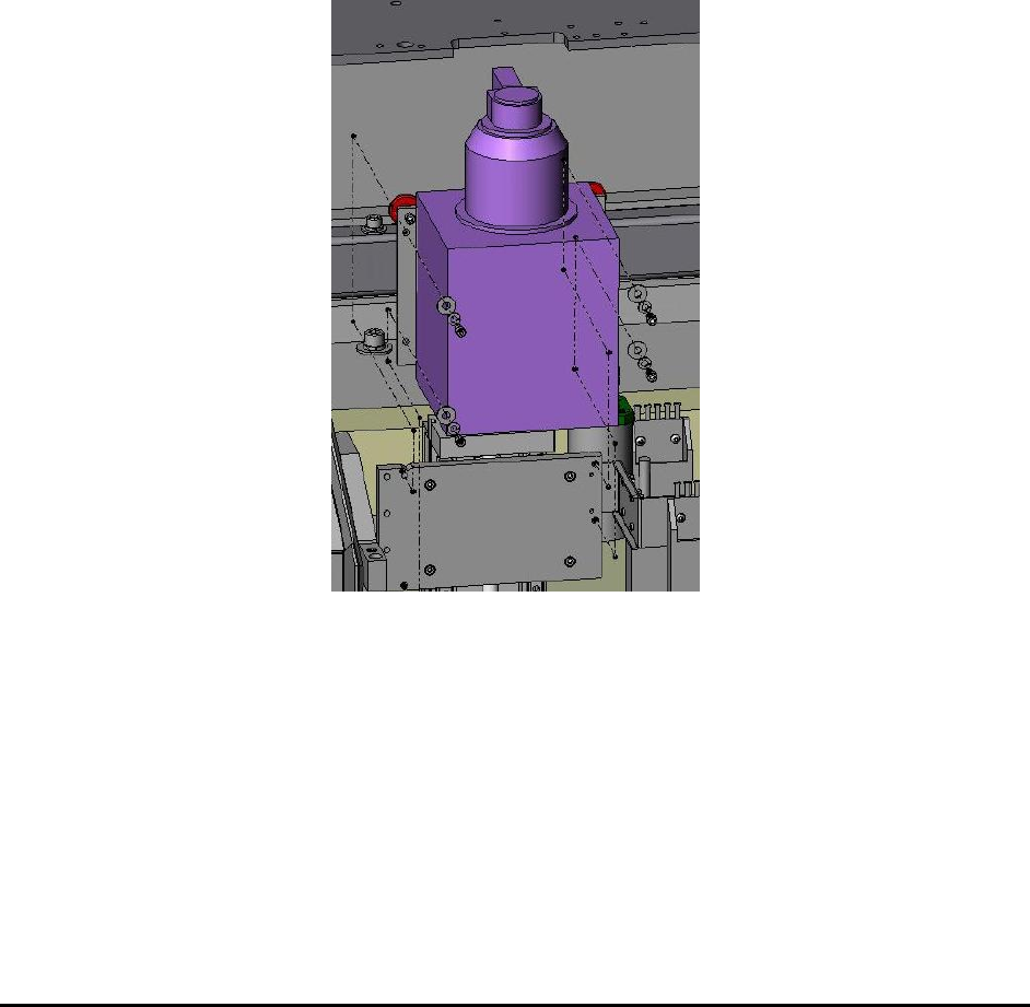
3.6 Install the X-ray Tube
To prevent damage during shipment, the X-ray tube is removed from the machine and shipped in
its own protective package. The X-ray tube needs to be installed into the machine during
installation. The X-ray tube is held by 4 (1 ½” length ¼ 20 thread) screws. A (3/16”) T-handle
Allen wrench is shipped with the system for those screws.
There is a protective stainless steel cover covering the X-ray emitting port. It needs to be
removed before operation.