CP-6-series Mechanical Reference.pdf - 第14页
Safety Guidelines Fuji machines are designed and pr oduced with safety as one of our main considerations. However , even a perfectly designed machine can be damaged, or someone can still be injured if the user does not f…

Contents – List of Current Pages
Edition 1.6 x CP-6-series Mechanical Reference
Part 9 Carrier Type Loading System
1. Carrier Type Loading System................................(Edition 1.0) ......9-1-1
2. In-Conveyor...........................................................(Edition 1.0) ......9-2-1
2.1 Adjustment of the Lifter Air Cylinder Sensors.................................................9-2-3
2.2 Mid-Stopper Position Alignment .....................................................................9-2-4
3. In-Carrier...............................................................(Edition 1.4) ......9-3-1
3.1 Adjustment of the In-Carrier Open/Close Limit Sensors.................................9-3-2
4. Main Conveyor......................................................(Edition 1.0) ......9-4-1
4.1 Adjustable Rail Engagement Sensor..............................................................9-4-2
4.1.1 Safety Measures ..........................................................................9-4-3
4.1.2 Adjusting the Sensor Position ......................................................9-4-4
4.1.3 Adjusting the Sensor Sensitivity (Amplifier Unit) ..........................9-4-5
4.2 Adjustment of the Clamper Open/Close Limit Sensors ..................................9-4-6
5. Out-Carrier............................................................(Edition 1.4) ......9-5-1
5.1 Adjustment of the Out-Carrier Open/Close Limit Sensors..............................9-5-2
6. Out-Conveyor........................................................(Edition 1.0) ......9-6-1
6.1 Adjustment of the Lifter Air Cylinder Sensors.................................................9-6-2
6.2 Mid-Stopper Position Alignment .....................................................................9-6-3
7. Setting the Board Positioning Pins........................(Edition 1.0) ......9-7-1
Part 10 Supplementary Information
1. Vibration Reduction Unit (CP-642E, CP-643E).....(Edition 1.0) ....10-1-1
1.1 Nomenclature ...............................................................................................10-1-1
1.2 Purpose and Operating Principle of Unit ......................................................10-1-2
1.3 Installation Procedure...................................................................................10-1-3
1.4 Air Valve Modification and Adjustment.........................................................10-1-5
1.5 Changing the Conveyor Link Bracket...........................................................10-1-6
2. Noise Levels..........................................................(Edition 1.0) ....10-2-1
Appendix Electronic Temperature Controller
A. Functions of Electronic Temperature Controller ...(Edition 1.0).........A-1
B. Directions for Use.................................................(Edition 1.0).........B-1
C. Troubleshooting....................................................(Edition 1.0).........C-1

Safety Guidelines
Fuji machines are designed and produced with safety as
one of our main considerations. However, even a
perfectly designed machine can be damaged, or someone
can still be injured if the user does not follow the safety
rules. It is the responsibility of the user to make sure all
safety rules are followed during operation and
maintenance.
Be sure to read these safety rules before operating the
machine.
Safety Guidelines
Edition 1.5 1 CP-6-series Mechanical Reference
1. About Symbols
(ESG0101a)
This section provides an explanation of the relevant safety precautions to be adhered to by both
operators and those responsible for maintaining the machine. An explanation of the warning
labels attached to the machine is also provided.
This manual employs the use of descriptive symbols and provides details of the level of danger
involved in certain operations to accompany the explanations of machine warning labels and
safety related items. Be sure you uderstand the meanings of these symbols before reading the
manual.
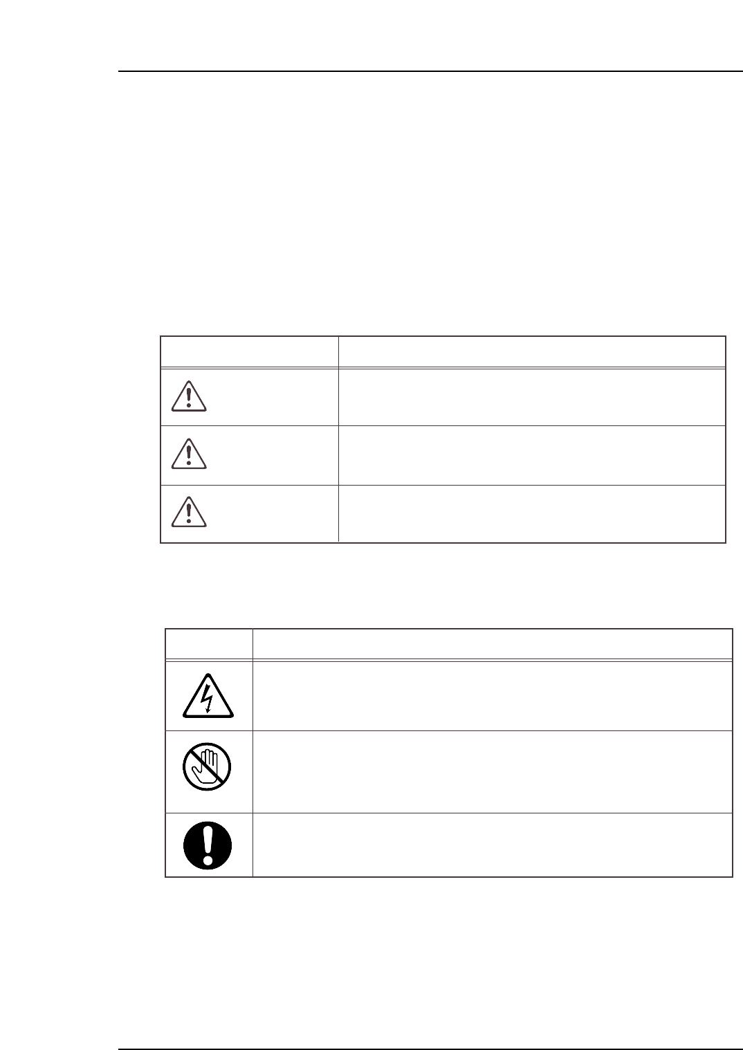
Hazard Definitions
Examples of Symbols Used
Hazard
A triangle is used to draw your attention to a hazard. The symbol inside
the triangle indicates the nature of the hazard (in this case, electrical shock).
Prohibition
A circle with a diagonal line is used to draw your attention to an operation
that is prohibited. The symbol inside the circle indicates the nature of the
operation (in this case, "Do not touch").
A circle is used to draw your attention to a mandatory action. In other words,
you are required to carefully carry out the given instructions.
Symbol Explanation
Failure to observe this hazard warning will lead to severe
injury or death.
DANGER
Failure to observe this hazard warning could lead to severe
injury or dath.
WARNING
Failure to observe this hazard warning may lead to personal
injury or damage to the machine
CAUTION
Symbol Definition