CP-6-series Mechanical Reference.pdf - 第233页
Part 7 Proper Data Measurements
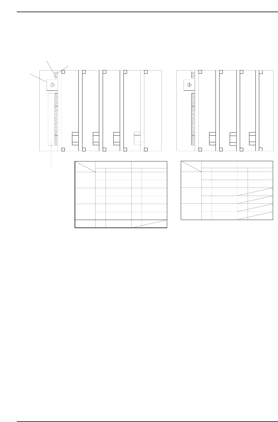
1.5 MX 250 I/O Configuration
This is the arrangement of the LEDs that display in control box 1 for MX 250 I/O boards.
0
1
2
3
4
5
6
7
8
9
A
B
C
D
E
F
2A. Fuse
2A. Fuse
2A. Fuse
I/O-1 I/O-2 I/O-3 I/O-4
INPUT OUTPUT
SW.# SW.#
Address Address
I/O-1
I/O-2
I/O-3
0
1
2
3
4
5
6
8
9
A
B
C
D
A00 ~ A0F
B00 ~ B0F
A00 ~ A0F
B00 ~ B0F
A00 ~ A0F
B00 ~ B0F
A00 ~ A0F
A00 ~ A0F
B00 ~ B0F
A00 ~ A0F
B00 ~ B0F
A00 ~ A0F
B00 ~ B0F
0
1
2
3
4
5
6
7
8
9
A
B
C
D
E
F
2A. Fuse
LI/O-1 LI/O-2
INPUT OUTPUT
SW.# SW.#
Address Address
LI/O-1
LI/O-2
0
1
2
3
4
5
8
9
A00 ~ A0F
B00 ~ B0F
A00 ~ A0F
B00 ~ B0F
A00 ~ A0F
B00 ~ B0F
A00 ~ A0F
B00 ~ B0F
Power ON
Transmission Error
Rotary Selector
Switch
I/O Function
Indicators
2A. Fuse
2A. Fuse
LI/O-3
LI/O-3
2A. Fuse
I/O-4
To monitor the I/O, simply select the proper inport or outport. Each I/O port controls 32 inputs and
outputs address number (listed in the System Reference Manual) and set the rotary selector switch as
indicated in the chart above.
Direct I/O
Loader I/O
CP6M6004
Part 6 Chapter 1 The Machine I/O
Edition 1.0 6-1-6 CP-6-series Mechanical Reference

Part 7
Proper Data
Measurements
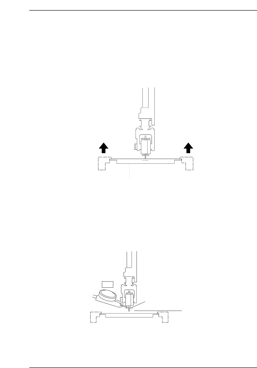
1. Z-Axis Origin Position (Zθ)
In order to offset board warpage and minute deviations in nozzle shaft placing height, Zθ, the Z-axis
reference placing height, is calibrated in order that the board rises to make contact with the part being
held by the nozzle and then pushes up a further 0.3 mm.
1.1 Zθ Measurement (CP-642)
1. Load the fiducial jig-plate onto the main conveyor as shown in the diagram below.
2. Using the inching keys, move the fiducial plate under station 11.
3. Switch the I/O (Y028 PLACE SOL ON) to ON.
4. Rotate the cam angle to 200°, ensuring that the jig-plate is situated directly
underneath the nozzle shaft.
5. With a 20 mm diameter backlight-plate facing downward, place the dial gauge
needle on the upper surface of the backlight disk and set to zero.
"0"
Nozzle Lower
Limit
20 mm Backlight Plate
CP6M7002
Fiducial Jig-Plate
0.3 mm
0.3 mm
CP6M7001
Part 7 Chapter 1 Z-Axis Origin Position (Z
θ
)
Edition 1.5 7-1-1 CP-6-series Mechanical Reference