CP-6-series Mechanical Reference.pdf - 第160页
Part 4 Chapter 5 Electric Power Supply Edition 1.3 4-5-2 CP-6-series Mechanical Reference Connecting the Power Supply DANGER Verify that the external power supply is off before performing this procedure. 1. Open the powe…

Edition 1.3 4-5-1 CP-6-series Mechanical Reference
Part 4 Chapter 5 Electric Power Supply
5. Electric Power Supply
Power Consumption
CP-6 : approximately 8.5 KVA
CP-6M, CP-642, CP-642M, CP-643E, CP-643ME, CP-65 : approximately 10.0 KVA
CP-652C : approximately 20.3 KVA
(Capacity of transformer)
Connect the machine to a power supply with a capacity more than specified above.
Voltage
The CP-6 series contains a multiple input transformer which allows the machine to be
used with the normal supply voltage in any country.
Before connecting the power supply to the machine, make sure that the transformer tap
position matches the actual voltage to be supplied to the machine.
(The transformer is normally set correctly for the destination country before the machine
is shipped from the Fuji factory.)
Power Supply Cable
Use a power supply cable with at least 22 mm
2
. (Power supply of 200~230 V)
Thin cables may overheat or cause drop in the supply voltage.
Part 4 Chapter 5 Electric Power Supply
Edition 1.3 4-5-2 CP-6-series Mechanical Reference
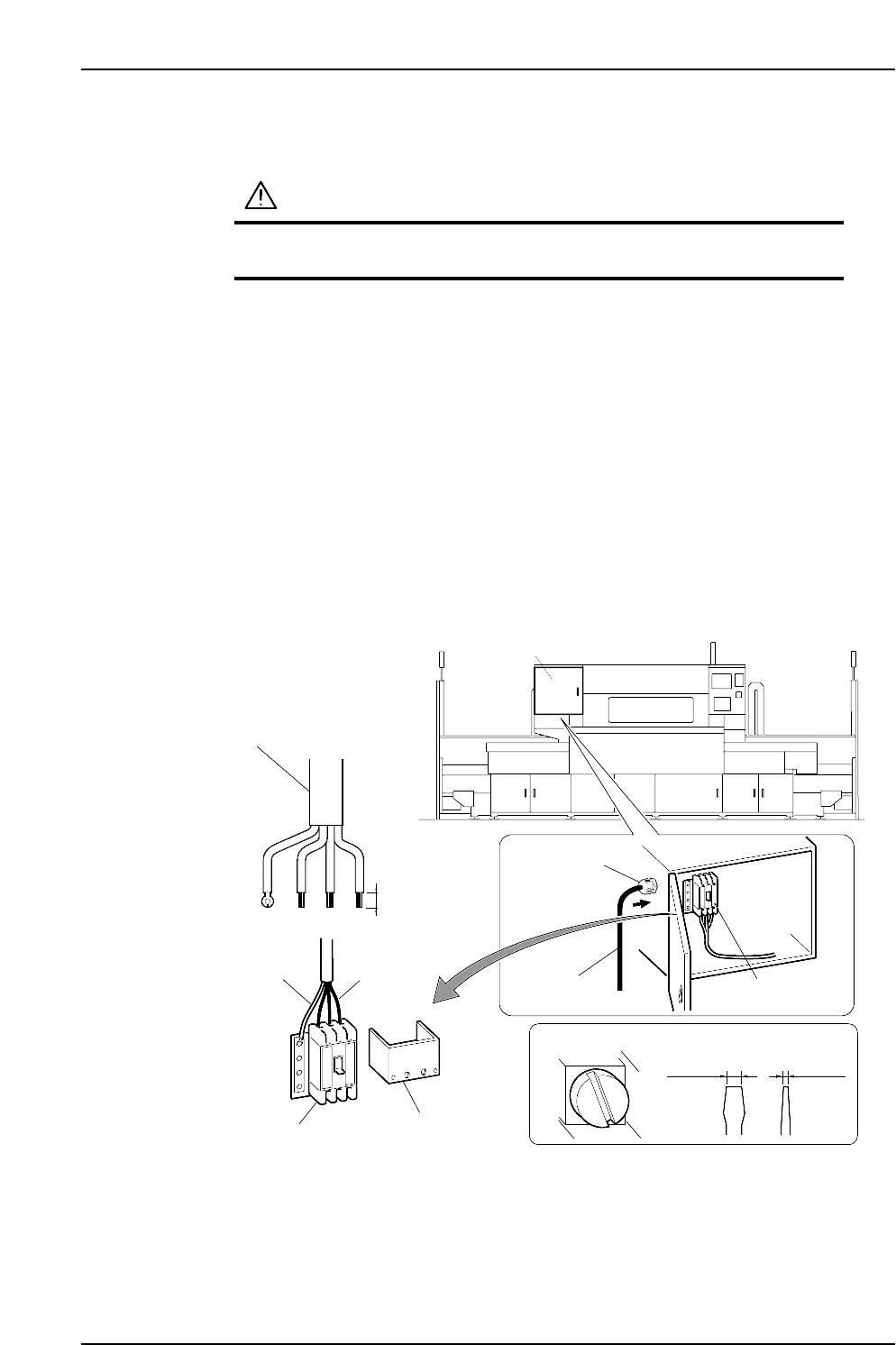
Connecting the Power Supply
DANGER
Verify that the external power supply is off before
performing this procedure.
1. Open the power box, then remove the transparent terminal cover.
2. Feed the power cable into the power box from the power cable inlet located at the
left side of the power box.
3. Connect the ground cable to the dedicated ground terminal.
4. Connect the 3-phase cable to the main breaker and tighten to the prescribed
torque.
Terminal screw tightening torque: 5.8 N⋅m (58 kgf⋅cm)
Note: Terminal screws should be tightened periodically.
5. After connecting the cable, secure it with the cable lock nut located at the power
cable inlet.
Cable lock nut tightening torque: 7.5 N⋅m (75 kgf⋅cm)
Power box
CP6MS026E
Three-phase
electric wire
Power cable
Power cable
Cable lock nut
Ground cable
Transparent
terminal cover
20 mm
Main breaker
Terminal screw
Recommended driver
8.0 mm 1.0 mm
Main breaker
Edition 1.3 4-5-3 CP-6-series Mechanical Reference
Part 4 Chapter 5 Electric Power Supply
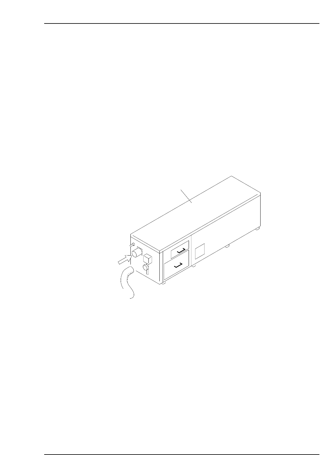
Checking the Three-Phase Cable Wiring
Follow the below steps to confirm that the three-phase wiring has been performed
correctly.
(1) Engage the 100 V power supply.
(2) Engage the 200 V power supply.
(3) Perform zero-setting.
(4) Press [AUTO]. Do not press the START button.
When [AUTO] is pressed, the vacuum pump in the noise reduction box at the rear of the
machine operates. Remove the hose to confirm that air is being sucked in. If air is being
sucked in, the wiring is correct and the motor is turning in the proper direction. If air is
being blown out, the user has crossed the U and V wires of the three-phase wiring.
Change these 2 wires and follow steps 1 to 4 again to confirm correct wiring.
Note: The CP-652C has a different shape of noise reduction box from the figure below. The
check procedure, however, is the same as stated above.
Noise reduction box
Air
CP6M4022