CP-6-series Mechanical Reference.pdf - 第56页
2.5 Electrical Control System 2.5.1 Operation Panels There are three operation panels on the machine. The controls needed to operate the machine are installed on each of these. Operation panel 1: Located on the front of …
For the CP-652C, make sure to adjust the width of the conveyor above the noise
reduction box as well.
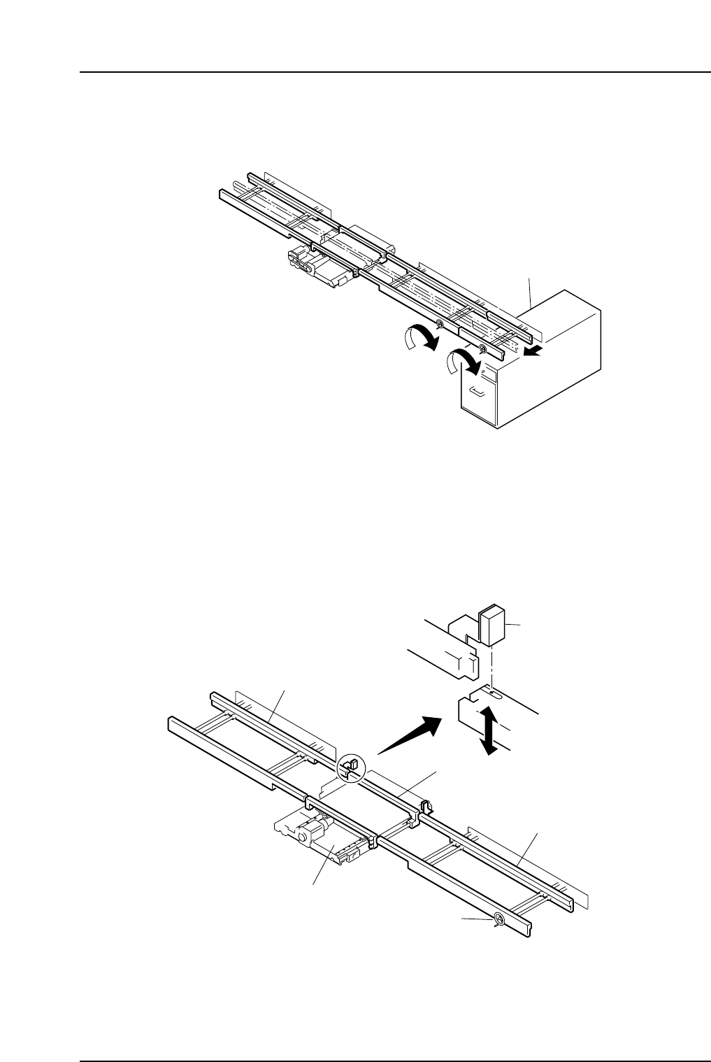
Moving Board Clamp Engagement Check
(CP-642/642E, CP-642M/642ME)
Special sensors have been installed on the CP-642 series to ensure the moving rails of the
in- and out-conveyors and the XY-table engage correctly when the XY-table is raised.
These sensors (shown in the diagram below) are active when the XY-table is in the
loading position.
Engagement check sensor
Moving board clamp lever
Out-conveyor
In-conveyor
XY-table
Handle
CP6M1028E
Noise reduction box
CP6M1027E
Part 1 Chapter 2 Functions of Each Component
Edition 1.1 1-2-16 CP-6-series Mechanical Reference
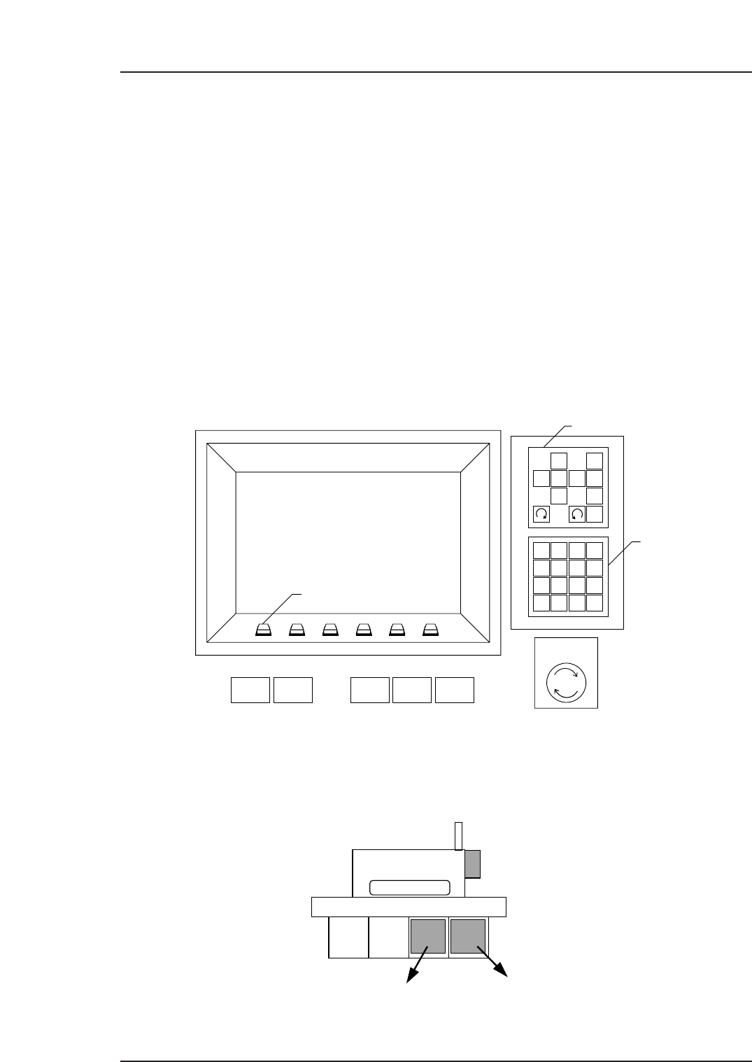
2.5 Electrical Control System
2.5.1Operation Panels
There are three operation panels on the machine. The controls needed to operate the
machine are installed on each of these.
Operation panel 1: Located on the front of the machine, this includes switches
necessary to operate the machine, an operation monitor and
a monitor for the vision processing carried out at station 6.
Operation panel 2: Located on the rear of the machine, this includes switches
necessary to operate the machine and an operation monitor.
Operation panel 3: Located on the central rear fence of the machine, this
(Models with fence) includes a front/rear panel operation selection key, a start
button, a CYCLE STOP button, a RESET button, and an
EMERGENCY STOP button.
Some machine types do not have this operation panel.
Control Boxes
The two control boxes, servo box and control box, are located on the lower front sides of
the machine. Also, there is a power box in the front upper left part of the machine.
CP-6
CP6M1030E
Control Box 1
Control Box 2
1
2
3
4
56
7
8
9
G
#
—
F
1
2
3
4
B
S
C
R
0
↑
←
↓
→
POWER
OFF
CYCLE
STOP
POWER
ON
START RESET
Inching Keys
Numerical
Keypad
EMERGENCY
STOP
Function Keys
✽
CP6M1029E
Part 1 Chapter 2 Functions of Each Component
Edition 1.1 1-2-17 CP-6-series Mechanical Reference
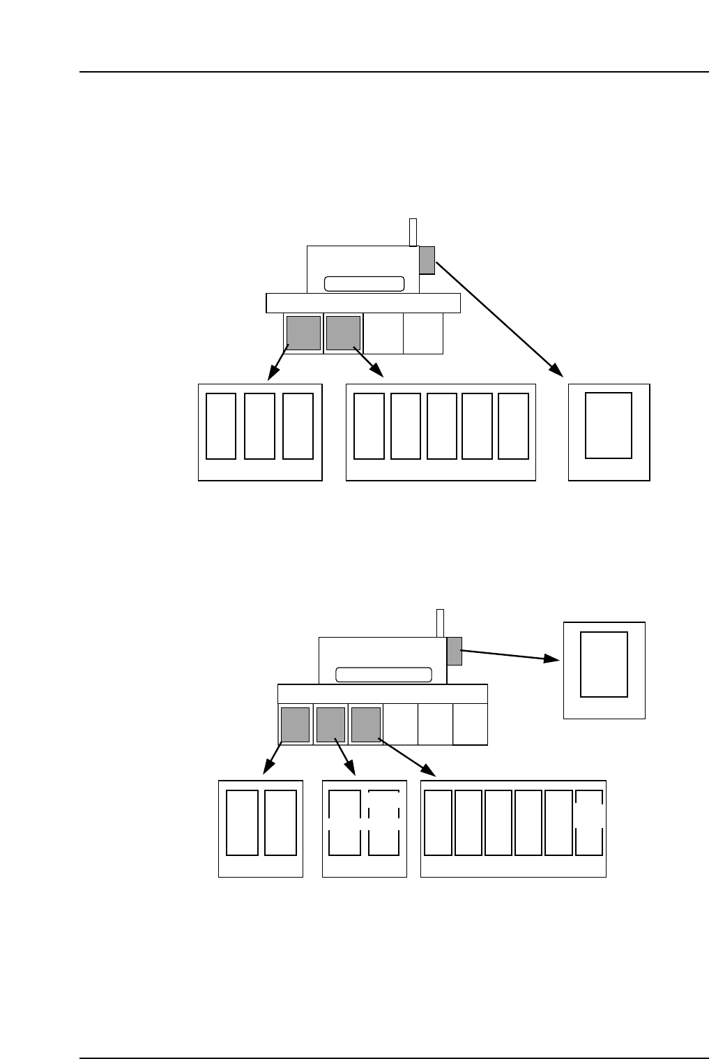
2.5.2Servo Boxes
The servo amplifiers for each axis can be found inside the servo boxes. Details of each
servo amplifier is given below.
<CP-6/6E, CP-6M/6ME, CP-642/642E, CP-642M/642ME, CP-643E/643ME, CP-65/65E>
<CP-652C>
CP-652C
CAM
DF
DR
UP
DOWN
YZ
FR
F θ
θ
NC
X
Nozzle
change
Servo box 1 Servo box 2 Servo box 3
Operation box 1
elevator elevator
CP6M1032E
X
Y
CAM
D2
D1
Z
FR
F θ
CP-6
θ
NC
(X)(D2)
**
Nozzle
change
Servo box 1 Servo box 2
Operation box 1
* The symbol in the parentheses is applied to the CP-642/642E, CP-642M/642ME,
CP-643E/643ME and CP-65/65E.
CP6M1031E
Part 1 Chapter 2 Functions of Each Component
Edition 1.1 1-2-18 CP-6-series Mechanical Reference