CP-6-series Mechanical Reference.pdf - 第302页
4.1.3 Adjusting the Sensor Sensitivity (Amplifier Unit) W ARNING Never look directly into the laser beam as this can damage the eyes. 1. Set the timer setting trimmer to 40 ms, the timer mode selector switch to OFF, and …
4.1.2 Adjusting the Sensor Position
WARNING
Never look directly into the laser beam as this can damage the eyes.
1. Perform the following command sequence to move the main table to the loading
position: [LOADER] - [LOADING PSTN] - START button.
2. Press the EMERGENCY STOP button to cut off the 200V power. Only the 100V
power should remain on.
WARNING
Turn off the 200 V servo power before carrying out this work.
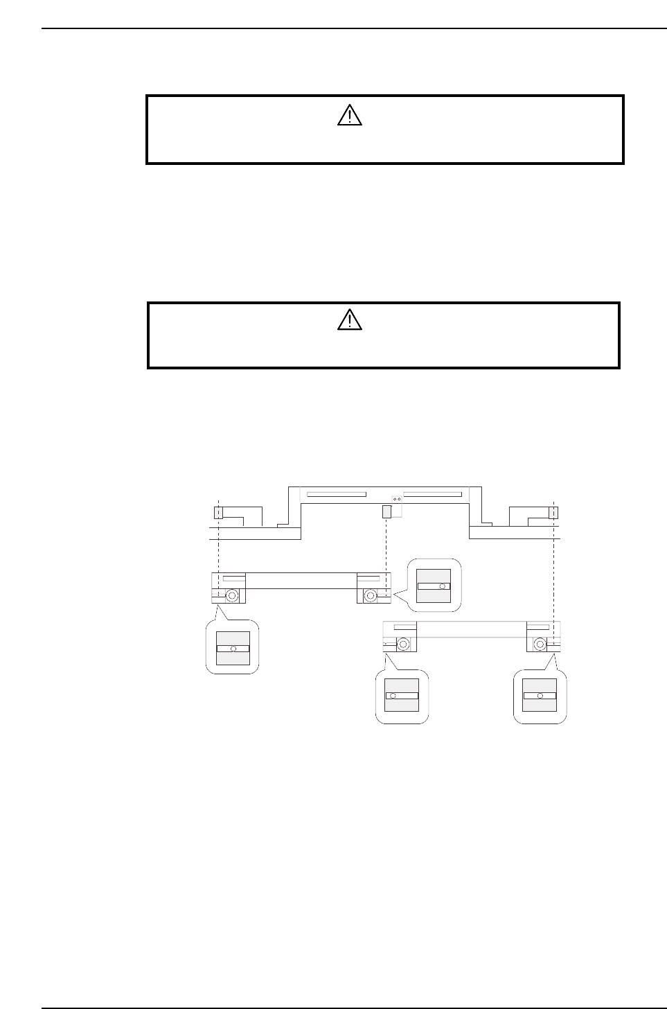
3. With the main conveyor’s adjustable rail engaged with the in- and out-conveyors’
adjustable rails, secure the sensor at the position where the seal’s silver area can be
detected.
Adjustable rail engagement
sensor 1
Adjustable rail engagement
sensor 2 Adjustable rail engagement
sensor 3
CP6M10020
(Toward the right)
(Center)
(Toward the left)
(Center)
IN loading
position
OUT loading
position
Part 9 Chapter 4 Main Conveyor
Edition 1.0 9-4-4 CP-6-series Mechanical Reference
4.1.3 Adjusting the Sensor Sensitivity (Amplifier Unit)
WARNING
Never look directly into the laser beam as this can damage the eyes.
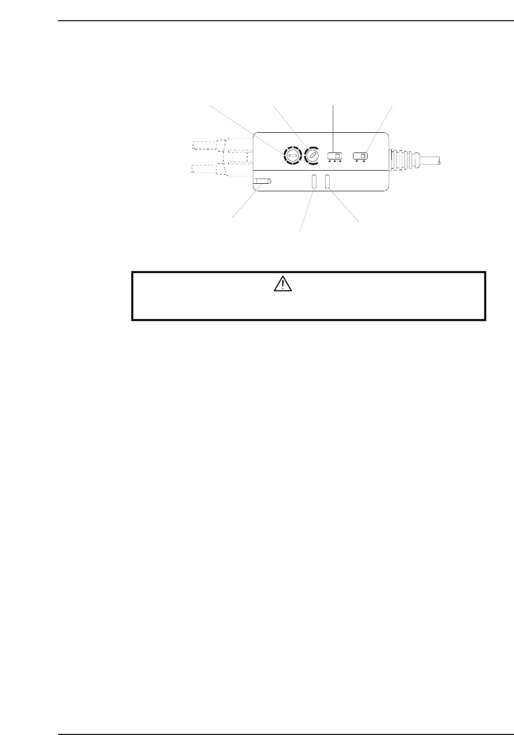
1. Set the timer setting trimmer to 40 ms, the timer mode selector switch to OFF, and
the operation mode selector switch to the “L ON” mode.
2. Adjust the sensitivity adjusting trimmer (SENS) until the following conditions are
obtained:
When the laser beam is striking the seal’s silver area at the adjustable rail, the
operation indicator (OUT) (red) and the stable operation indicator (STB) (green)
should be ON.
When the laser beam is striking the seal’s black area, the operation indicator (OUT)
(red) and the stable operation indicator (STB) (green) should be OFF.
3. Check the sensor inputs at the I/O screen using the following command sequence:
[I/O] - [Standard I/O] - [IN].
X034 FLWUP RAIL OUT
X035 FLWUP RAIL IN
Timer mode
selector switch
Operation mode
selector switch
Timer setting
trimmer
Sensitivity adjusting
trimmer
Laser emission indicator
Operation indicator
Stable operation indicator
L ON
D ON
MODE
OFF
ON D
OFF D
5s
TIMER
40ms
SENS
LASER
ON
STB
OUT
CP6M10021
Part 9 Chapter 4 Main Conveyor
Edition 1.0 9-4-5 CP-6-series Mechanical Reference
4.2 Adjustment of the Clamper Open/Close Limit Sensors
Adjustment
WARNING
• Turn off the 200 V servo power before carrying out this work.
• The CP-643E/643ME conveyor is equipped with laser sensors.
In areas where there is a risk of eye damage from the laser beams,
be sure to install a laser beam shield at the laser emission area
before performing this sensor adjustment procedure.
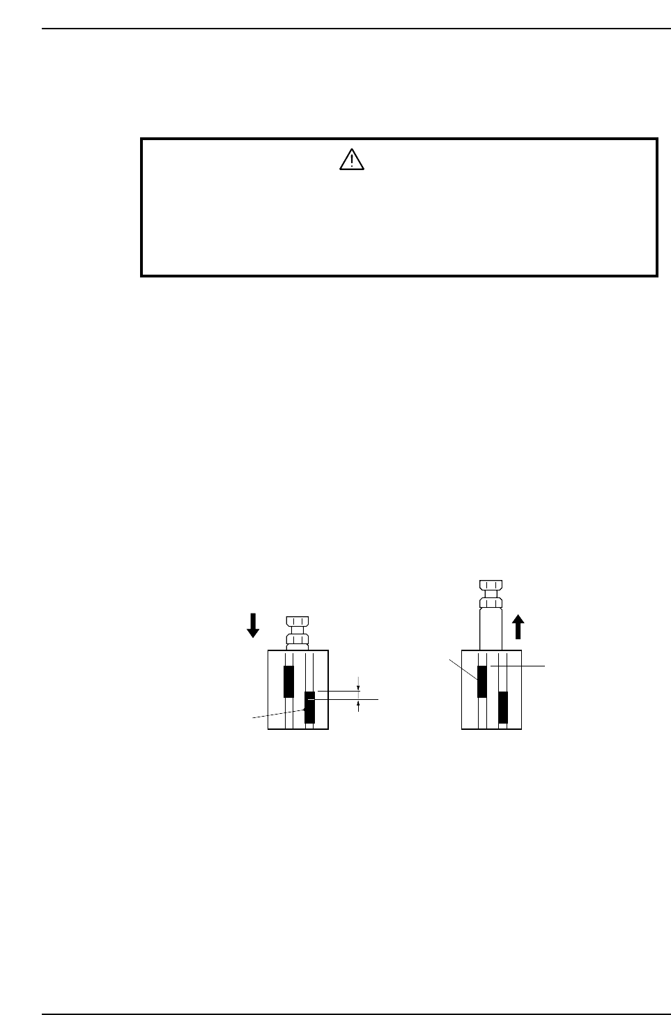
1. Release the air inside the cylinder.
2. Set the cylinder in the contracted status and check the position at which the open
limit sensor comes ON.
3. Open limit sensor: Move the sensor upward 0.5 mm from the ON position, and
secure it in place.
Close limit sensor: Clamp two boards (in succession) of two different
thicknesses. Secure the close limit sensor at the position
where the following conditions are satisfied.
<On mark reference machines>
• ON when 4.0 mm thickness board is clamped
• OFF when 4.3 mm thickness board is clamped
<On pin reference machines>
• ON when 4.5 mm thickness board is clamped
• OFF when 5.0 mm thickness board is clamped
b
Close limit sensor
a: Position at which the open limit sensor comes ON with the cylinder in the contracted status
b: Position at which the close limit sensor switches ON when 4.0 mm (or 4.5 mm) thickness
board is clamped, and OFF when 4.3 mm (or 5.0 mm) thickness board is clamped.
CP6M10022
a
Open limit sensor
0.5 mm
When unclamped When clamped
Part 9 Chapter 4 Main Conveyor
Edition 1.0 9-4-6 CP-6-series Mechanical Reference