CP-6-series Mechanical Reference.pdf - 第47页
Belt T ension (CP-642/642E, CP-642M/642ME, CP-643E/643ME) Set the XY-table belt tension as shown in the figure below. The tension at the front side (when looking from the front of the machine) should be set to 100.0 ± 2.…
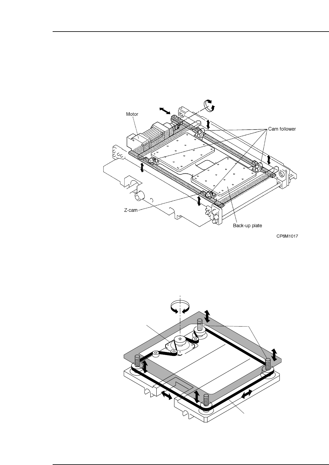
As shown in the figure below, the Z-axis motor rotates to move the rack and pinion
system, moving the LM guides left and right. On the LM guides there are four angled
cams. As the LM guides move, the cam followers slide over the cams, raising or
lowering the Z-axis.
CP-6/6E, CP-6M/6ME, CP-65, CP-652C
On CP-642 and CP-643 series, there is a ballscrew at each corner of the table. These
ballscrews are rotated by means of timing a belt which is driven by a servo motor. The
Z-aixs is raised or lowered as the ballscrews rotate.
CP-642/642E, CP-642M/642ME, CP-643E, CP-643ME
Motor
Ball screw
Timing Belt
CP6M1018
Part 1 Chapter 2 Functions of Each Component
Edition 1.1 1-2-7 CP-6-series Mechanical Reference
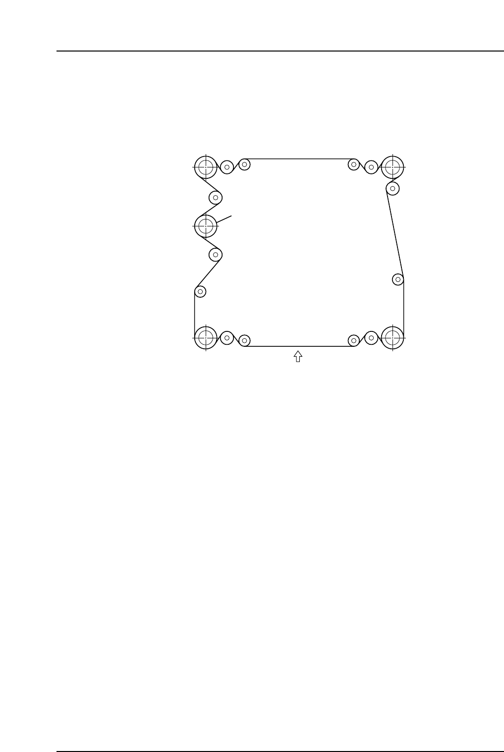
Belt Tension (CP-642/642E, CP-642M/642ME, CP-643E/643ME)
Set the XY-table belt tension as shown in the figure below. The tension at the front side
(when looking from the front of the machine) should be set to 100.0 ±2.0 Hz. Use a
tension gauge to carry out the measurement.
100.0 ± 2.0 Hz
Motor
CP6M1019E
Part 1 Chapter 2 Functions of Each Component
Edition 1.1 1-2-8 CP-6-series Mechanical Reference
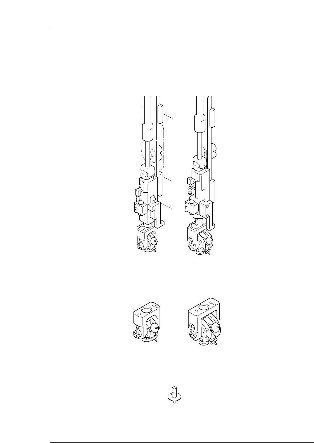
2.1.4The Placing Head
The Head
The head has a holder attached as shown below.
The Holder
The holder has the nozzle assembly attached as shown below.
The Nozzle
The nozzle picks parts using suction force which is supplied by a vacuum situated at the
rear of the machine.
CP6M1022
(4000 TYPE) (5000 TYPE)
CP6M1021E
(4000 TYPE) (5000 TYPE)
CP6M1020E
Part 1 Chapter 2 Functions of Each Component
Edition 1.1 1-2-9 CP-6-series Mechanical Reference