CP-6-series Mechanical Reference.pdf - 第228页
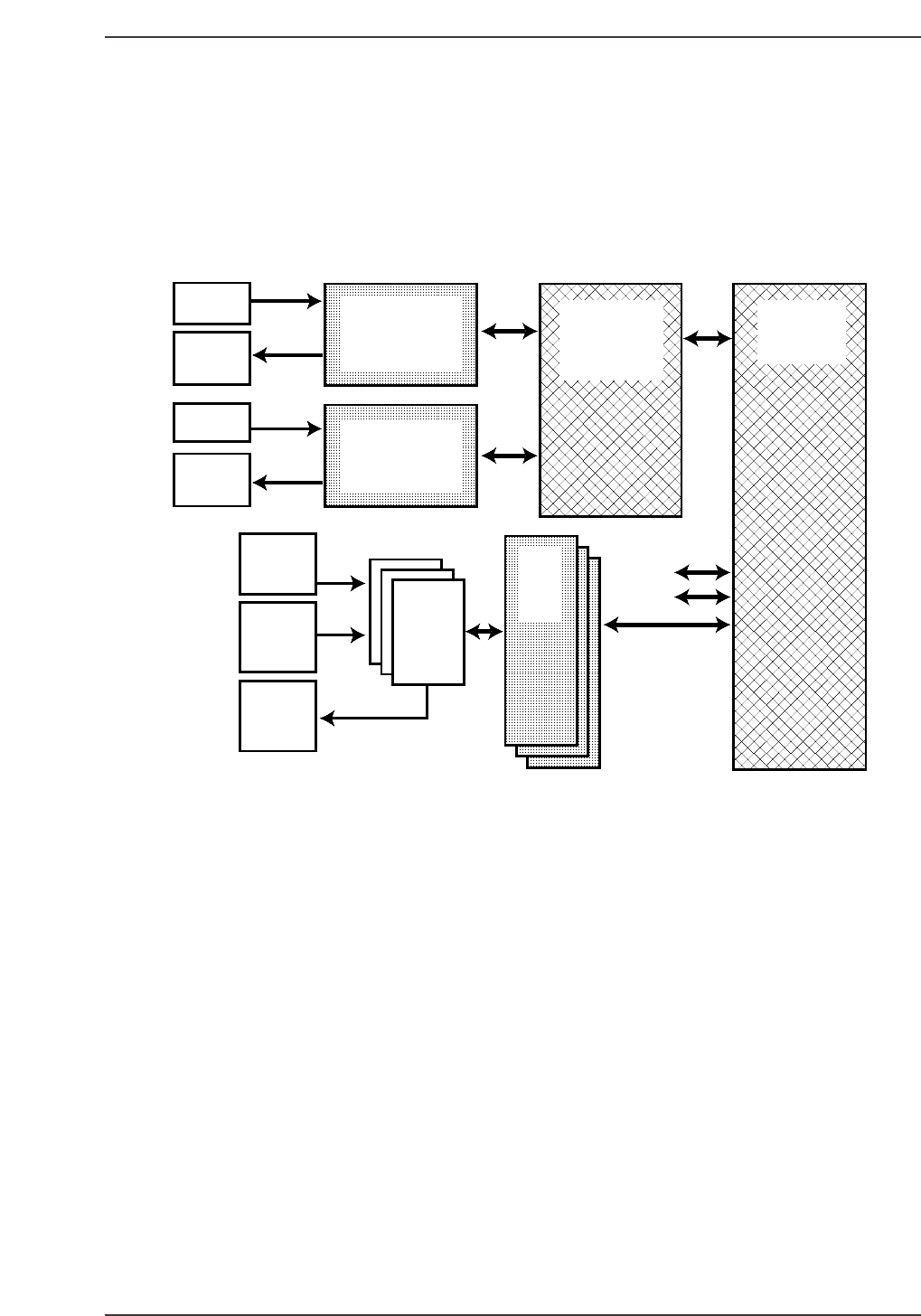
1.1 Major Components The machine’s I/O system is comprised of the CPU card, 3 servo cards, the VME interface card, 2 PLC’s, 3 servo I/O interface cards and the various relays, sensors and motors of the machine. CPU Card …
1. The Machine I/O
I/O is an acronym for input/output. Each sensor, solenoid, relay, etc. in the CP-6 is controlled by the
I/O. The input portion receives signals from the machine (i.e. sensors). The outputs drive devices in
the machine (i.e. solenoids, relays, etc.).
X
Y
LX
LY
SX
Sensors
Servo I/O
10 PCB1
11 PCB1
12 PCB1
PC-1
Main Machine I/O
MX100 PLC
PLC-1
Loader I/O
MX100 PLC
CP91
VME
INTERFACE
Board
HIMV-134
CPU Board
Servo
PCB's
1, 2, 3
1570B
Zero Set.
OT & ILK
Sensors
Servo Amp
ALRM &
RDY
Signals
Relay
Control
Circuits
Relays
Solenoids
Lamps
Loader
Sensors
Loader
Solenoids
& Motors
Input Output
X = Direct I/O Input Y = Direct I/O Output
LX = Loader I/O Input LY = Loader I/O Output
SX (1,2 &3) = Servo Card Input SY (1,2 &3) = Servo Card Output
I/O Arrangement
CP6M6001
Part 6 Chapter 1 The Machine I/O
Edition 1.0 6-1-1 CP-6-series Mechanical Reference

1.1 Major Components
The machine’s I/O system is comprised of the CPU card, 3 servo cards, the VME
interface card, 2 PLC’s, 3 servo I/O interface cards and the various relays, sensors and
motors of the machine.
CPU Card HMV 134
All machine functional decisions are made here. The CPU uses the various input signals
to control/confirm desired functions, while using the output signals to initiate these
functions. Many of the alarms that appear on the machine monitor can be traced back
through the I/O.
Servo Cards IS70B
These cards interface the CPU card to the servo amplifiers, but “Connector 4” on each of
the cards monitors the zero set sensors and overtravel sensors for the servo axes
controlled by that card.
VME Interface Card MX250V01
This board interfaces the VME bus (mainly the CPU card) to the Programmable Logic
Controllers (PLC’s). For an output, the decision is made by the CPU to turn on/off a
port (relay, solenoid, LED, etc.) and the signal travels to this card via the VME bus. The
card then routes the signal to the proper PLC (either the direct I/O or the loader I/O
PLC). The actual switching signal is sent by the PLC (usually to a relay), which actually
drives the device (solenoid, valve, etc.). The input side works the same way but in an
opposite path.
Programmable Logic Controllers (PLC) MX100 / MX 250
FUJI has steered toward the mainstream and away from direct VME I/O controls. The
VM-1540 has been eliminated from new FUJI SMT machines. In its place, PLC’s now
perform the function of I/O management. There are two PLC’s in the CP-6. The larger
of the two is called the “Direct I/O PLC”. It handles all main machine inputs and
outputs. The second PLC is called the “LOADER PLC”. It controls only loader functions
(i.e. anything related to the conveyer).
This PLC consists of four portions: CPU, Input module, Output Module and the Relay
Module. The CPU module controls the other three. It is driven by logic found on a
control ROM located under the blue access panel. Modules of the same type are
interchangeable and may be swapped.
Part 6 Chapter 1 The Machine I/O
Edition 1.0 6-1-2 CP-6-series Mechanical Reference

1.2 The I/O Menu
Accessing the I/O
There are three ways to access the status of the I/O on the CP-6 series machines:
a. Through the machine menus
Each input and output has its own separate name and address which may be seen by
pressing [SET], [MANUAL] and [I/O].
b. Direct I/O Entry
The alternate method of entering the I/O, called direct I/O entry, may also be initiated
by:
1. Turning the machine OFF.
2. Hold the black F1 key down.
3. Press the POWER ON key.
4. Keep the F1 key held down until the first color (I/O) menu comes up.
c. Visual Observation of the PLC LEDs.
This procedure puts the operator directly into the I/O. The main purpose of this mode is
for troubleshooting. The machine should be turned off after troubleshooting is
completed.
Part 6 Chapter 1 The Machine I/O
Edition 1.0 6-1-3 CP-6-series Mechanical Reference