CP-6-series Mechanical Reference.pdf - 第87页
<5000 type> 1. Press [LOADER] - [LOADER PSTN] followed by the START button to move the XY-table to the loading position. 2. Press [LIFTER ▲ ]to raise the XY-table to the same height as the in/out-conveyor. 3. Press…
4.3 Settings for Fiducial Mark Reference
Point
When the reference and follow-up pins are not used, and the machine only uses the
fiducial marks as a reference, follow the steps listed below.
Procedure
<4000 type>
1. Select [LOADER] - [LOADING POSTN], and press the START button to move the
XY-table to the loading position.
2. Press [LIFTER s] and the XY-table is raised to the same height as the in- and out-
conveyors.
3. Press the EMERGENCY STOP button.
WARNING
Turn off the 200 V servo power before carrying out this work.
4. Unscrew the pivot pin. (Models other than CP-642, CP-642M, CP-643E, and
CP-643ME)
5. Unscrew the pin holder set.
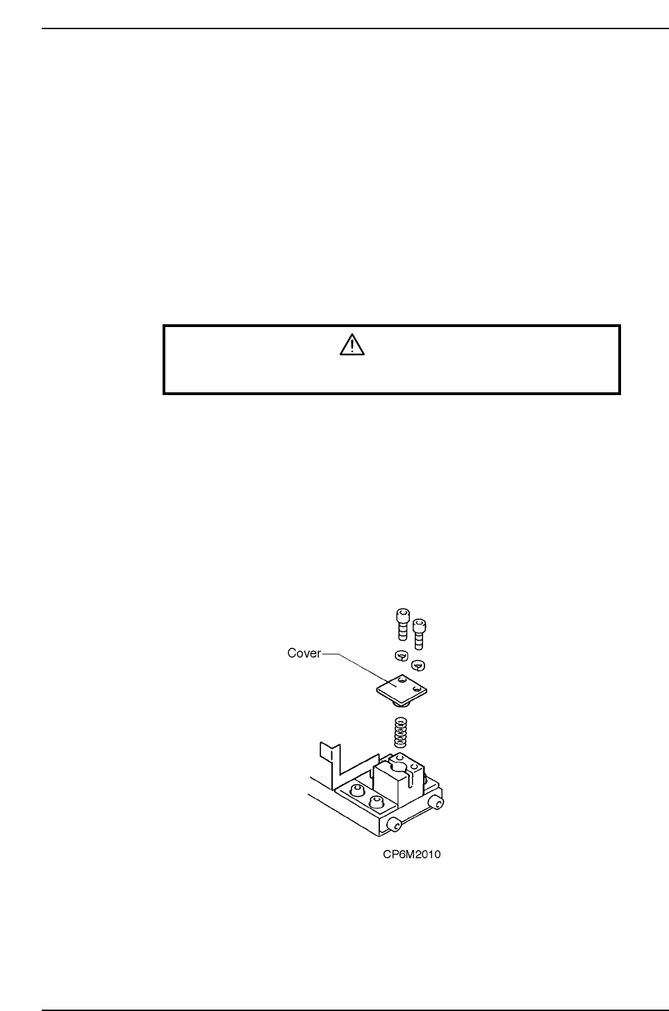
6. Remove the pin and holder from the block. Be careful that the spring loaded
beneath the pin does not shoot the pin out.
7. While the spring is in the block, attach the cover to the reference pin block. While
the dog is attached, check to see if the spring pin (attached to the cover) is in the
slot cut in the metal dog. Attach the cover.
8. It is not necessary to remove the follow-up pin. The pin can be moved outside the
size of the board that is being produced.
Part 2 Chapter 4 Board Positioning Pins
Edition 1.0 2-4-4 CP-6-series Mechanical Reference
<5000 type>
1. Press [LOADER] - [LOADER PSTN] followed by the START button to move the
XY-table to the loading position.
2. Press [LIFTER ▲]to raise the XY-table to the same height as the in/out-conveyor.
3. Press the EMERGENCY STOP button.
WARNING
Turn off the 200 V servo power before carrying out this work.
4. Unscrew the pin holder bolts.
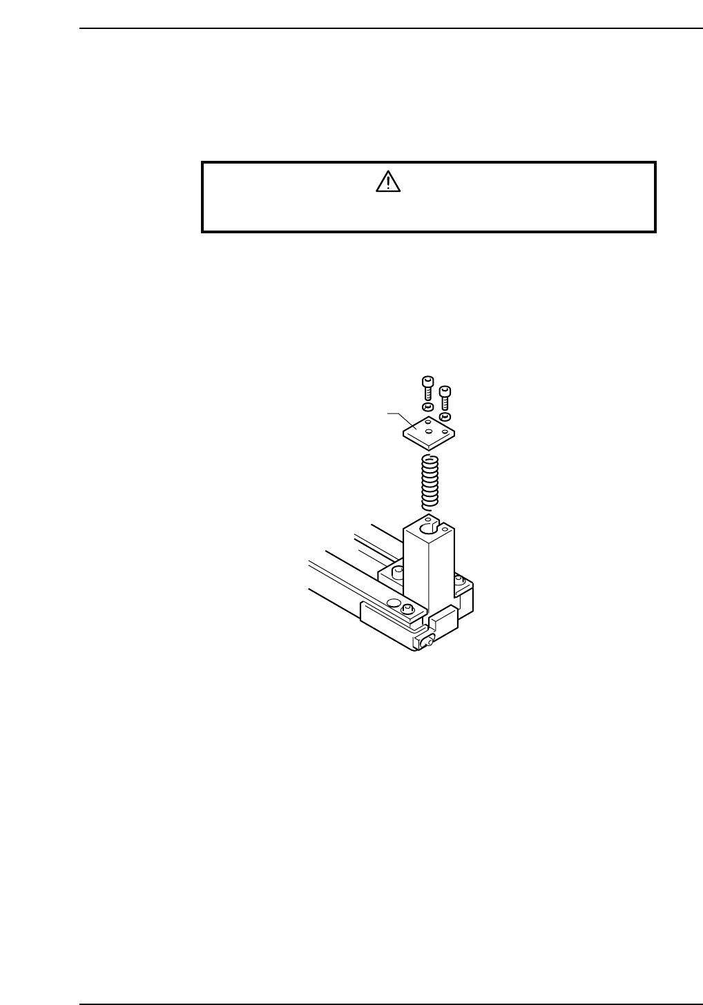
5. Remove the pin and holder from the block. Be careful that the spring beneath the
pin does not shoot the pin out.
6. With the spring in place, put the cover on the reference pin block.
7. It is not necessary to remove the follow-up pin. Position the pin outside the size of
the board that is being produced.
Cover
CP6M2011
Part 2 Chapter 4 Board Positioning Pins
Edition 1.0 2-4-5 CP-6-series Mechanical Reference

Notes:
Part 2 Chapter 4 Board Positioning Pins
Edition 1.0 2-4-6 CP-6-series Mechanical Reference