CP-6-series Mechanical Reference.pdf - 第210页
3.6 Station 12 Fine-reverse Mechanism This mechanism reverses the nozzle rotation performed at station 10 for part placement. 3.6.1 Clutch Meshing Check W ARNING • Turn off the 200 V servo power before carrying out this …
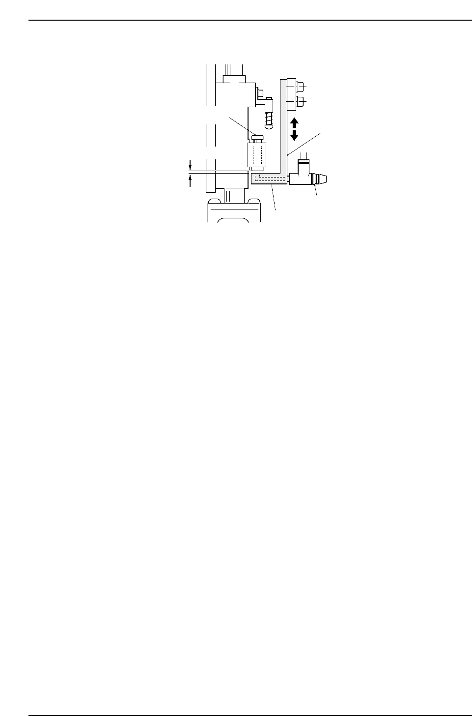
6. Ensure that the spool and the lever are not in physical contact.
Note: Take care when touching the speed regulator.
(The speed regulator should be set four or five rotations away from the completely closed
position.)
0.05 ~ 0.1 mm
Bracket
Speed regulator
Lever
Spool
CP6M5055
Part 5 Chapter 3 Station Adjustments
Edition 1.0 5-3-34 CP-6-series Mechanical Reference
3.6 Station 12
Fine-reverse Mechanism
This mechanism reverses the nozzle rotation performed at station 10 for part placement.
3.6.1 Clutch Meshing Check
WARNING
• Turn off the 200 V servo power before carrying out this work.
• Exercise extreme caution when working on the machine if the cam is
not at its origin (0 deg.). Recoil of the cam axis can endanger the
operator.
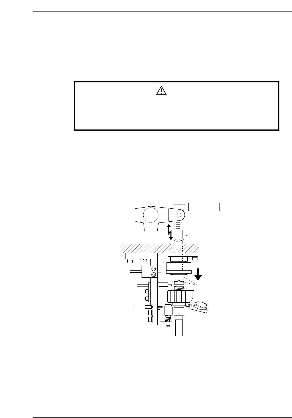
Perform this check on the low-pressure nozzle.
1. Set a dial gauge to the lower surface of the slide stopper.
2. Use the cam handle to rotate the cam to 200°.
3. Ensure that the clutches mesh properly and the pressure applied is 0.3 ~ 0.35 mm.
Note: The low-pressure nozzle refers to the nozzle axis (out of the 20) that receives the weakest
pushing pressure. Use the low-pressure nozzle for meshing checks at stations 3, 5, 10, 12
and 13.
Station 12
Rod
Clutches
0.30 ~ 0.35 mm
CP6M5056
Part 5 Chapter 3 Station Adjustments
Edition 1.0 5-3-35 CP-6-series Mechanical Reference
3.6.2 Meshing Check Sensor
WARNING
• Turn off the 200 V servo power before carrying out this work.
• Exercise extreme caution when working on the machine if the cam is
not at its origin (0 deg.). Recoil of the cam axis can endanger the
operator.
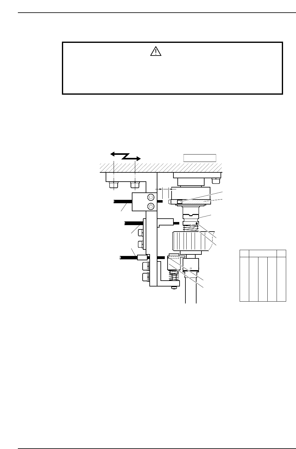
This sensor checks whether or not the clutch is correctly engaged when fine theta reverse
and/or nozzle origin positioning is performed. Check that the sensor LED (red) is OFF
when the clutch is correctly engaged and ON when the clutch is not correctly engaged.
Set the amp volume so that it operates as shown in the following figure. Refer to
“Nozzle Detection Sensor”of 3.9 “Station 17” of this chapter for the adjustment method.
Station 12
ON (flag)
Clutch
ON (hole)
OFF
OFF (hole)
ON
FR Zero set sensor
Nozzle origin position sensor
Meshing check sensor
5 mm
OFF
15st
12st
10st
Zero-setting
Meshing check
Clutch origin
Zero-setting
Nozzle origin
θ
CP6M5057
Part 5 Chapter 3 Station Adjustments
Edition 1.0 5-3-36 CP-6-series Mechanical Reference