CP-6-series Mechanical Reference.pdf - 第52页
Preventing Device T able Collisions Since the two device tables work independently, an interlock is used to prevent collisions when they are working in close proximity to each other. Two types of interlock systems are us…
2.2 Parts Supply System
2.2.1Feeders
This feeds the tape on which parts are mounted to the pick-up position at station 1. Only
the CP-6-series feeders can be used on the CP-6-series machines.
2.2.2Device Tables (except for CP-652CE)
Located behind the machine, the device table consists of left and right tables,
servomotors, ball screws and related parts.
The device table is the location where the feeders are mounted. Tape feeders are set up
on the device table in the arrangement specified in the placing program. During
production, the device tables move the feeders directly under station 1 in the order
specified in the program. Station one nozzle then lowers and picks up the part.
The two device tables can be operated as a single unit or two separate units. The
following three modes are available:
Table Mode Selection
• Device change mode : When a parts related error occurs, the other table is
automatically selected.
• Changeover mode : Only one table operates at a time. The other table is
automatically selected at the end of the current program.
• Joint mode : In joint mode, the two tables move as one.
The above table selections are possible. Each device table has its own motor and can
work independently of the other. In the joint mode, the two device tables move in
synchronicity.
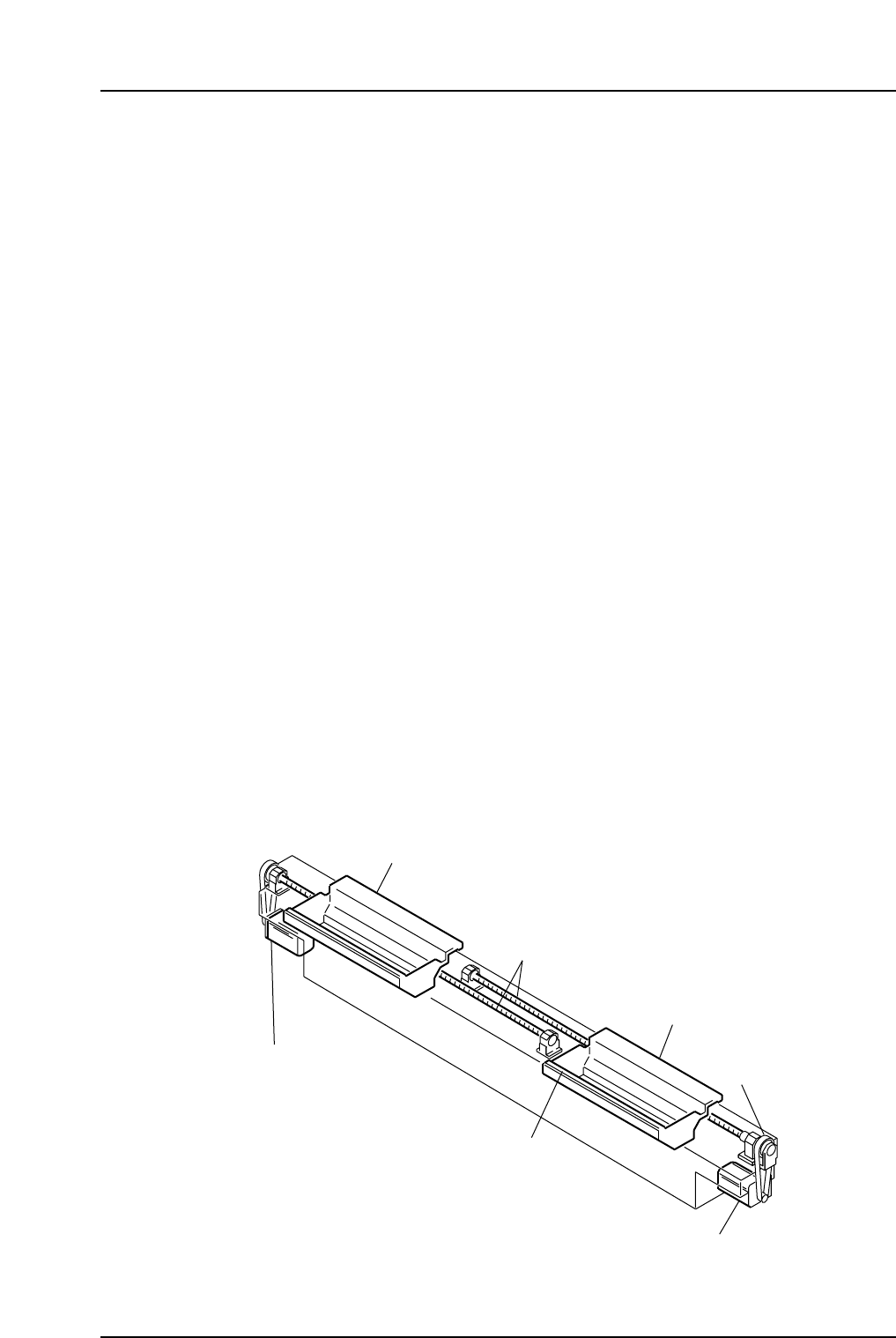
Device Table Configuration
The major components are shown in the following figure.
D1-axis motor
Table 1
Table 2
Timing belt
Tape feeder vibration
reduction assembly
D2-axis motor
Ball screws
CP6M1024E
Part 1 Chapter 2 Functions of Each Component
Edition 1.1 1-2-12 CP-6-series Mechanical Reference
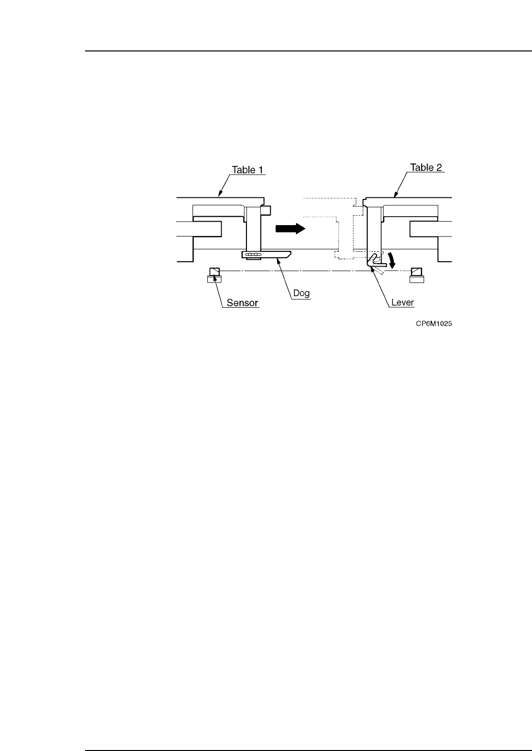
Preventing Device Table Collisions
Since the two device tables work independently, an interlock is used to prevent collisions
when they are working in close proximity to each other.
Two types of interlock systems are used. One is controlled using the software and the
other is controlled using the mechanical unit (sensor detection).
The sensor detection interlocking system is depicted in the following figure.
When the tables approach each other, a dog presses down on a lever. This lever
interrupts the sensor beam causing the machine to stop.
2.2.3Tape Cutter
Located behind the placing head at station 1 a vertical blade cuts against a ridge to cut
any tape which has extended past the end of the feeder.
The waste tape gets sucked through a vacuum hose into the waste tape collection box at
the rear of the machine.
2.2.4Pallet Feeder (Only for the CP-652C)
This device is used to transport pallets loaded with tape feeders.
It is composed of the pallets, setup stations, elevators, return conveyor, and related parts.
Pallets: All tape feeders are loaded on pallets for transport.
D-axis carrier: This transports pallets on the D-axis. This unit is driven by
the servo-motor to the position specified in the placing
program.
Setup stations: This unit facilitates removal or placement of tape feeders by
the operator.
Elevators: Elevators are of two types: for lifting and for lowering.
A pallet lifted by elevator is transferred to the D-axis. A
pallet lowered by elevator is transported to the return
conveyor.
Return conveyor: This conveyor transports pallets from the out-side to the in-
side.
Pallet pushers: This is driven by a pneumatic cylinder.
A pallet on an in-elevator is pushed toward the in-side setup
station, and a pallet on the D-axis carrier is expelled toward
the out-side setup station.
Part 1 Chapter 2 Functions of Each Component
Edition 1.1 1-2-13 CP-6-series Mechanical Reference

2.3 Vision System
2.3.1Parts Cameras
This system includes a wide and a narrow CCD camera, frontlighting and backlighting
system, a CCD camera mounting bracket and other related parts.
These cameras perform vision inspection of individual parts for the purpose of placing
position and angular compensation, etc.
2.3.2Mark Read Camera
This system includes a CCD camera, light, CCD camera mounting bracket and related
parts.
The camera reads the fiducial marks on the board to perform corrections to the position
of the board.
Part 1 Chapter 2 Functions of Each Component
Edition 1.1 1-2-14 CP-6-series Mechanical Reference