CP-6-series Mechanical Reference.pdf - 第216页
3.9.2 Sensor Interference Prevention It is possible to set the amplifier frequencies so that no interference occurs between the sensors even though the sensors are very close together. 1. Move the amplifier ’ s mode chan…
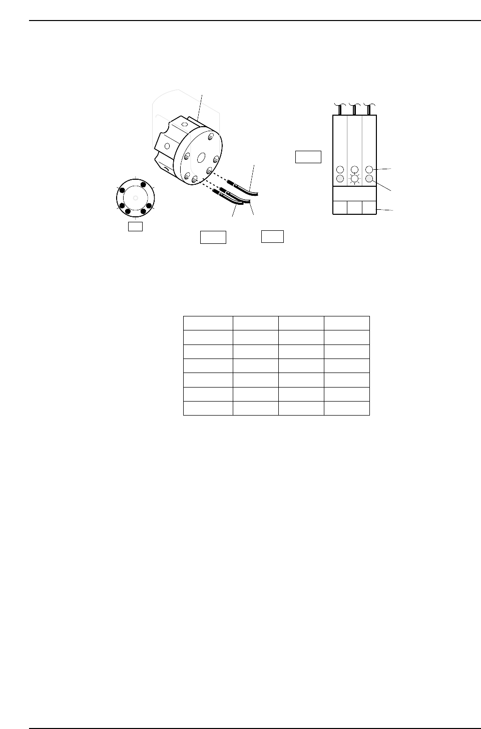
2. Rotate the rotary holder to select nozzle No. 2.
The sensor readings should be the same as shown below.
3. Ensure that the sensors display for the other nozzles as shown below.
Status of Red LED
Nozzle 1
Nozzle 2
Nozzle 3
Nozzle 4
Nozzle 5
Nozzle 6
Sensor 1
ON
OFF
OFF
ON
OFF
ON
Sensor 2
OFF
ON
OFF
ON
ON
OFF
Sensor 3
OFF
OFF
ON
OFF
ON
ON
CP6M5063
1
2
6
5
4
3
Rotary holder
Sensor 2
Sensor 1
Sensor 3
ON
OFF
Front of amplifier
Green LED
Red LED
Sensor No.
OFF
1
17st
3
2
CP6M5062
Part 5 Chapter 3 Station Adjustments
Edition 1.0 5-3-40 CP-6-series Mechanical Reference
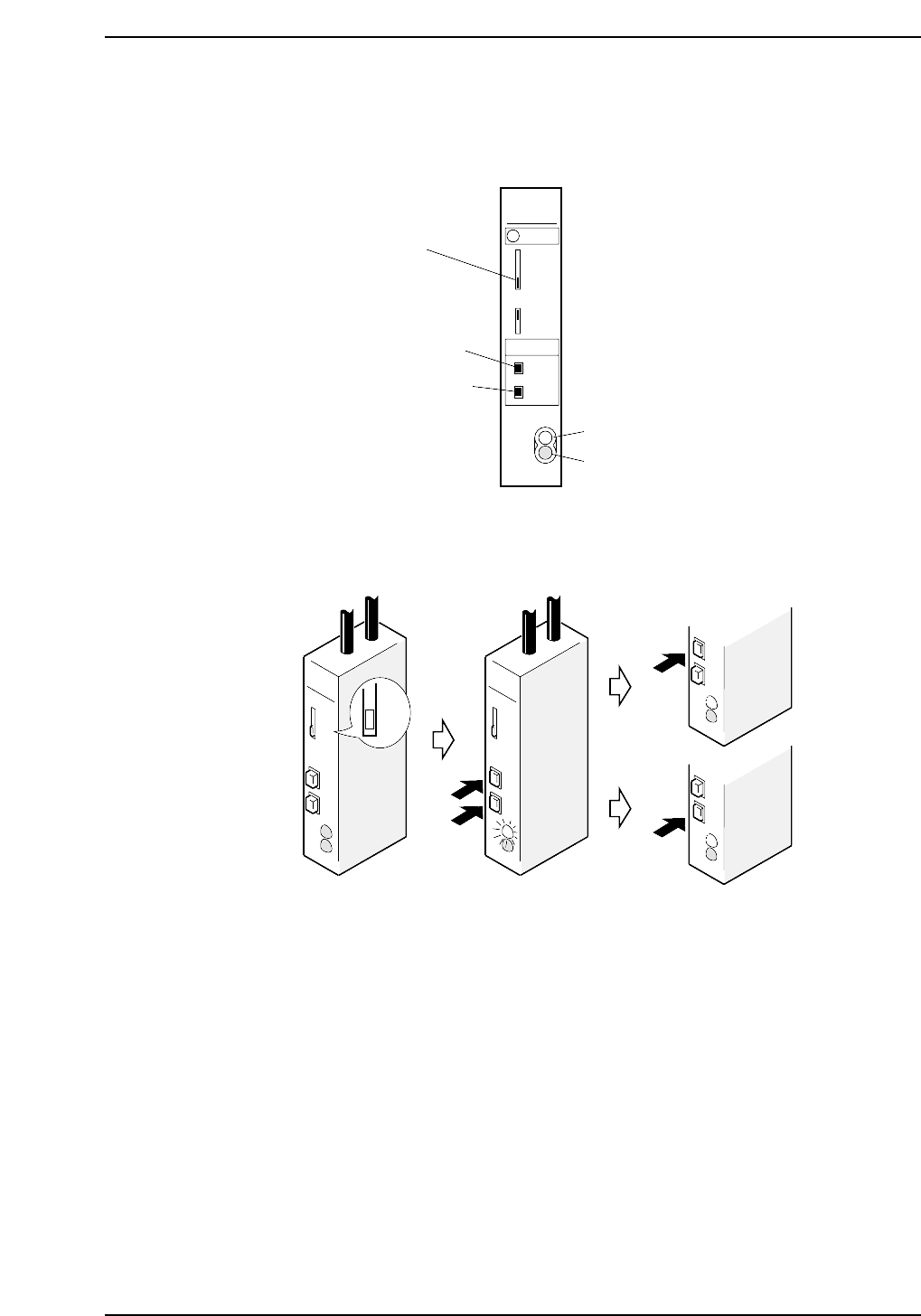
3.9.2 Sensor Interference Prevention
It is possible to set the amplifier frequencies so that no interference occurs between the
sensors even though the sensors are very close together.
1. Move the amplifier’s mode changing switch to SET.
2. Press the ON and OFF buttons simultaneously to cause the green LED to flash.
3. Press the ON button to set frequency A and the OFF button to set frequency B.
SET
SET
ON
OFF
ON
OFF
ON
OFF
ON
OFF
SET
(1)
(2) (3)
A
B
CP6M5065
SUNX
RUN
SIF
SET
NON
OFD
FX-7
ON
OFF
STB
OUT
ON button
OFF button
Mode changing
switch
Green LED
Red LED
CP6M5064
Part 5 Chapter 3 Station Adjustments
Edition 1.0 5-3-41 CP-6-series Mechanical Reference
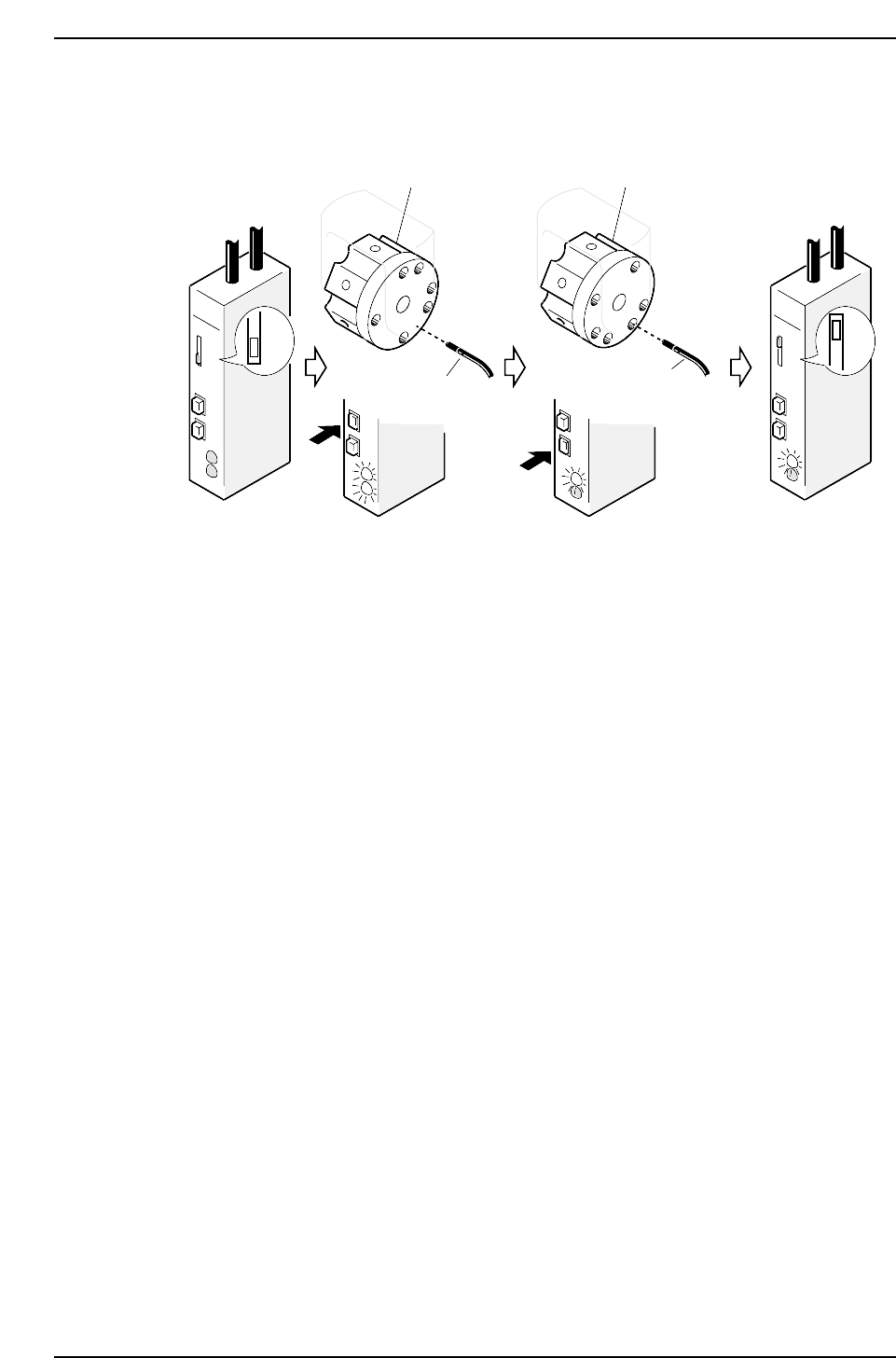
3.9.3 Sensor Sensitivity Adjustment
<When using sensors manufactured by SUNX>
1. Move the amplifier’s mode changing switch to the SET position.
2. Rotate the rotary holder until the sensor goes on (to a place other than a hole).
3. Press the ON button, both the red and green LEDs will then flash two or three
times and then go constant.
4. Rotate the rotary holder to an OFF position (to a hole).
5. Press the OFF button, the green LED will then flash two or three times and then go
constant.
6. Set the mode changing switch to RUN, the green LED will then start to flash. It is
possible to check the sensitivity condition by counting the number of time the LED
flashes.
No. of flashes: 0 ~ 4 5
Sensitivity: Bad Good
The setting is complete if the LED flashes five times.
7. Perform the following settings once again if the number of LED flashes is less than
five.
• Check connection between the amplifier and the fiber-optic cable.
• Confirm that the frequencies of each sensor are set so no light beam interference
occurs.
SET
ON
OFF
ON
OFF
ON
OFF
RUN
ON
OFF
RUN
SET
Rotary holder
Sensor 3
Rotary holder
Sensor 3
CP6M5066
Part 5 Chapter 3 Station Adjustments
Edition 1.0 5-3-42 CP-6-series Mechanical Reference