CP-6-series Mechanical Reference.pdf - 第207页
4. While observing the dial gauge, rotate the cam axis in the forward direction to raise the nozzle UP/DOWN rod. Adjust the sensor ’ s mounting position so that the sensor switches OFF (I/O INPORT X03F ST11 DN POS switch…
Nozzle DOWN Limit Sensor
Note: When performing the DOWN limit sensor adjustment after the UP limit sensor adjustment,
remove the dial gauge from the machine to avoid interference between the dial gauge and
the cam lever.
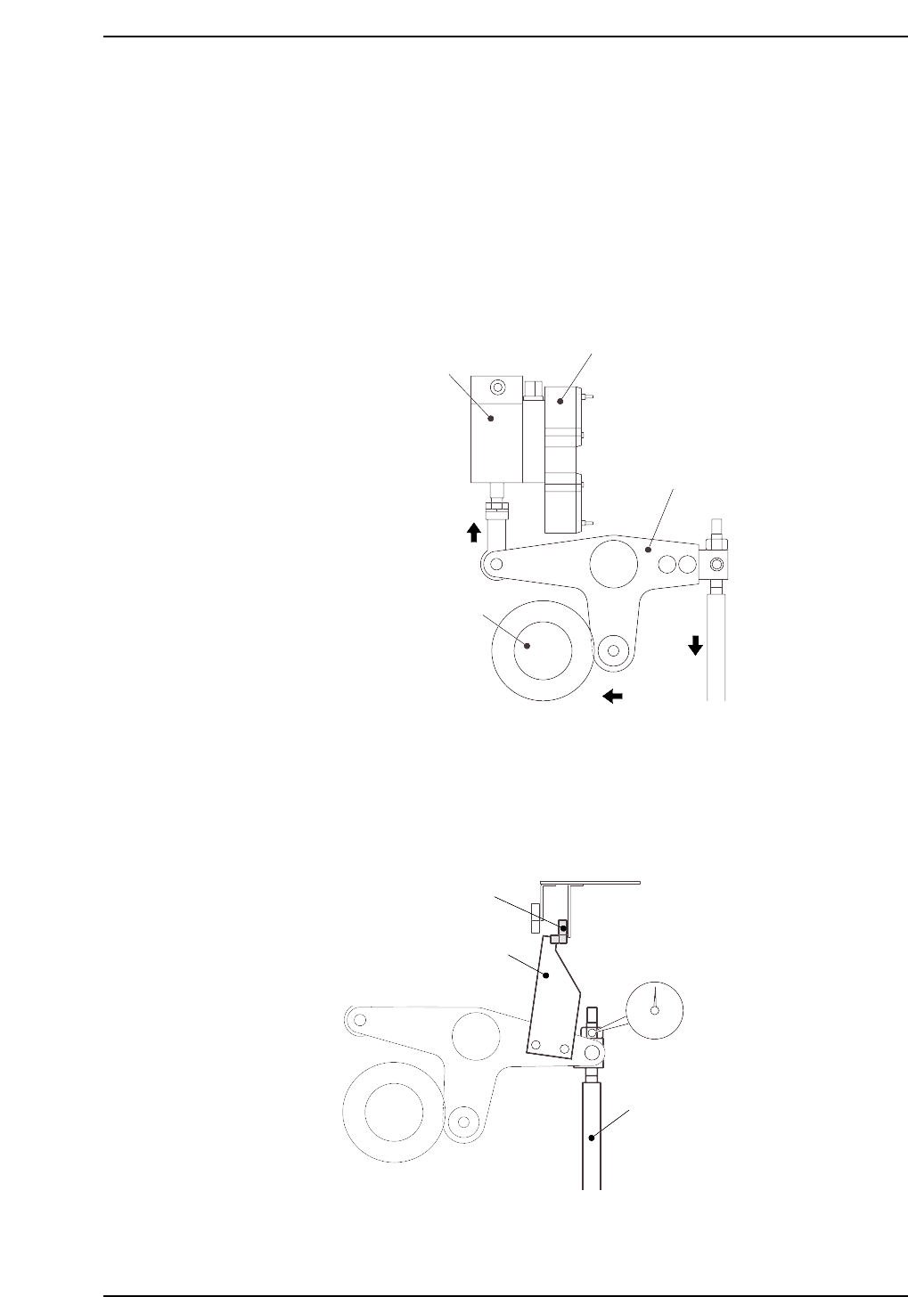
1. Set the cam axis to the 180-degree position.
2. Execute the following I/O commands to pull in the ST 11 placing stop cylinder
(located in the cam box):
[SET] - [MANUAL] - [I/O] - [Standard I/O] - [OUTPUT] -> Y028 PLACE SOL ON
The cam lever will then follow the cam axis.
3. Place a dial gauge on the nozzle UP/DOWN rod and set the gauge reading to “0”.
In this condition, the cam axis will be at its 180-degree position, and the nozzle
UP/DOWN rod will be at its DOWN limit position. Verify that the nozzle DOWN
limit sensor is ON (I/O INPORT X03F ST11 DN POS is ON).
CP6M5051
Nozzle DOWN limit sensor ON
Dog
Nozzle UP/DOWN rod
Set dial gauge to “0”
Solenoid valve
ST11 placing stop cylinder
Cam lever
Cam axis
CP6M5050
Part 5 Chapter 3 Station Adjustments
Edition 1.0 5-3-31 CP-6-series Mechanical Reference
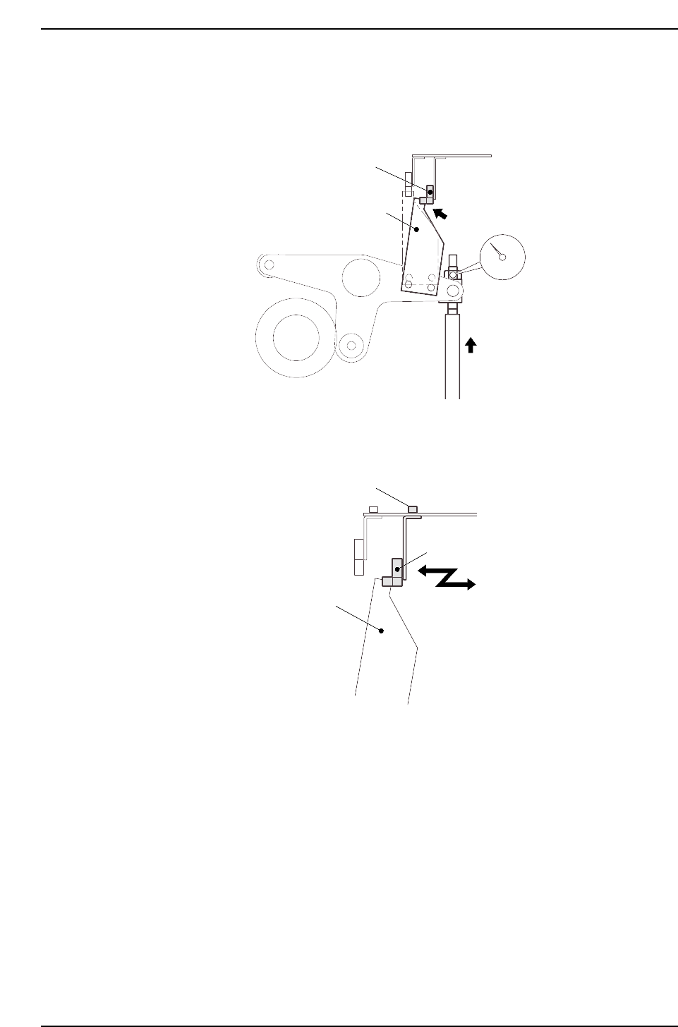
4. While observing the dial gauge, rotate the cam axis in the forward direction to
raise the nozzle UP/DOWN rod. Adjust the sensor’s mounting position so that
the sensor switches OFF (I/O INPORT X03F ST11 DN POS switches OFF) when
the rod has been raised 0.3 to 0.4 mm.
5. Adjust the sensor’s mounting position by loosening the sensor lock screws and
sliding the sensor in the front/back directions.
CP6M5053
Sensor
Lock screws
Dog
CP6M5052
Nozzle DOWN limit sensor OFF
Dog
Rod raised
0.3 to 0.4 mm
Part 5 Chapter 3 Station Adjustments
Edition 1.0 5-3-32 CP-6-series Mechanical Reference
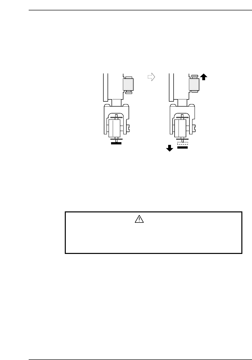
3.5.3 Nozzle Vacuum Off
The nozzle vacuum goes from ON to OFF with the movement of the mechanical valve at
station 11. Vacuum pressure inside the nozzle releases for part placement when the
valve closes. Ensure the part is placed on the production board.
Nozzle Vacuum Lever Adjustment
1. Adjust the valve ON/OFF operation at the reference head.
The reference head is ascertained by raising each spool as shown in the figure
above and measuring its height. The lowest head is used as the reference.
2. Select [SET] - [MANUAL] - [I/O] and then press the EMERGENCY STOP button
to take the 200V down to 100V.
WARNING
• Turn off the 200 V servo power before carrying out this work.
• Exercise extreme caution when working on the machine if the cam is
not at its origin (0 deg.). Recoil of the cam axis can endanger the
operator.
3. Set the cam angle to 0°, then turn on the nozzle vertical movement solenoid (Y028
PLACE SOL ON) for the nozzle at station 11 to work the lever.
4. Use the cam handle to rotate the cam to 200°.
5. Adjust the height of the bracket so that the distance between the spool and the
lever is 0.05 ~ 0.1 mm (This measurement can be made with a feeler gauge).
Vacuum ON Vacuum OFF
CP6M5054
Part 5 Chapter 3 Station Adjustments
Edition 1.0 5-3-33 CP-6-series Mechanical Reference