CP-6-series Mechanical Reference.pdf - 第262页
Adjust the shock absorbers for table advance and retraction. 1. Move the setup station to the fully retracted end of the pneumatic cylinder. 2. Turn the nut to adjust the position of the shock absorber. Make the shock ab…
3.7 Adjustment of the Shock Absorbers
Warning
Turn off the 200 V servo power before carrying out this work.
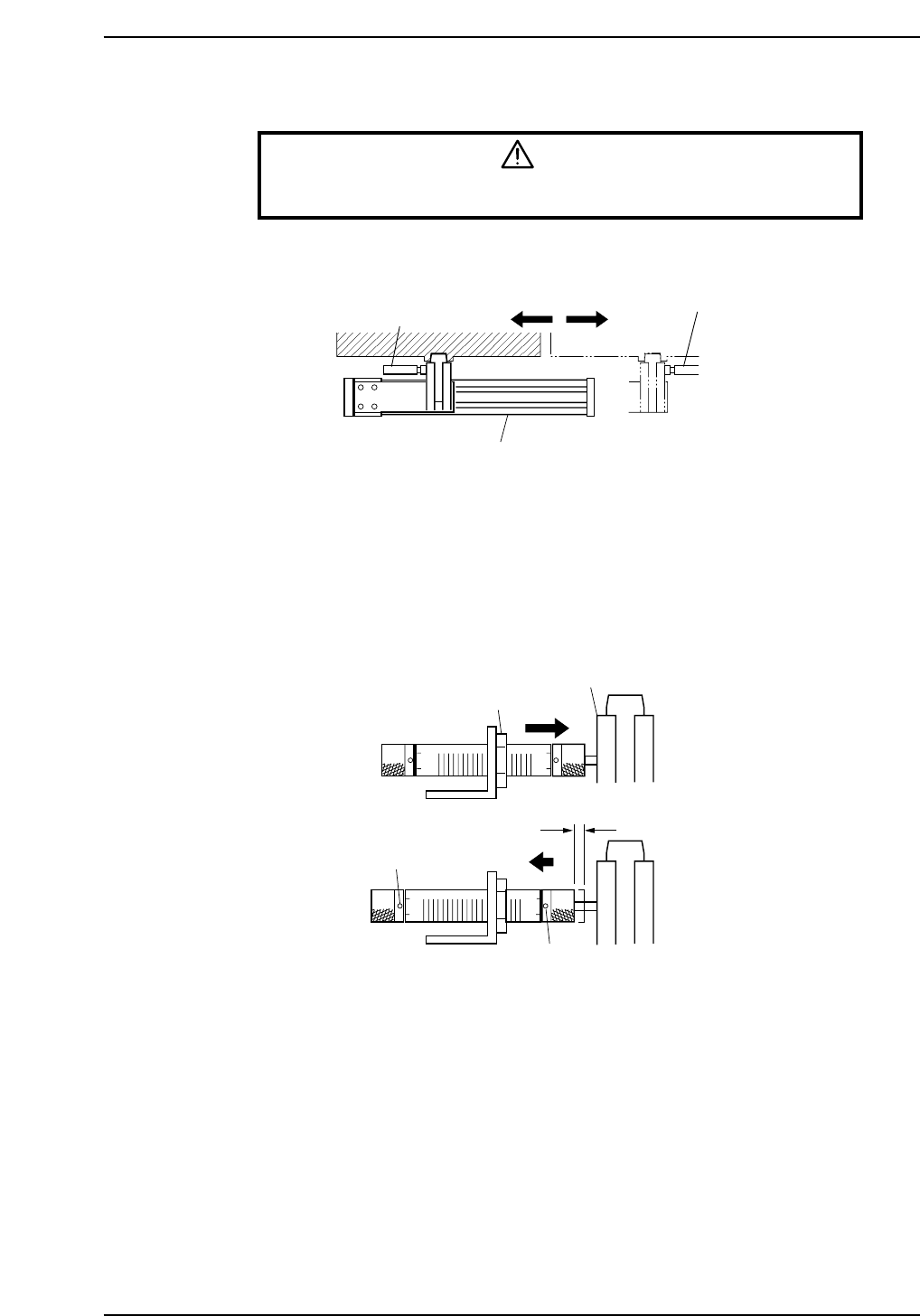
Adjust the shock absorbers for pallet feed.
1. Move the clamping unit to the stroke end of the pneumatic cylinder.
2. Turn the nut to adjust the position of the shock absorber.
Make the shock absorber come into contact with the clamp and press it in by an
amount corresponding to one full stroke (12.0 mm).
Return the shock absorber by 0.5 to 1.0 mm from this point, then secure it in place.
3. Set the scale indicator at "4.5".
4
5
54
4
5
5
4
0.5-1.0 mm
Scale indicator
Scale indicator
Nut
Clamp
CP6M9016
Shock absorber
Shock absorber
Pneumatic cylinder
CP6M9015
Part 8 Chapter 3 Setup Station
Edition 1.0 8-3-5 CP-6-series Mechanical Reference
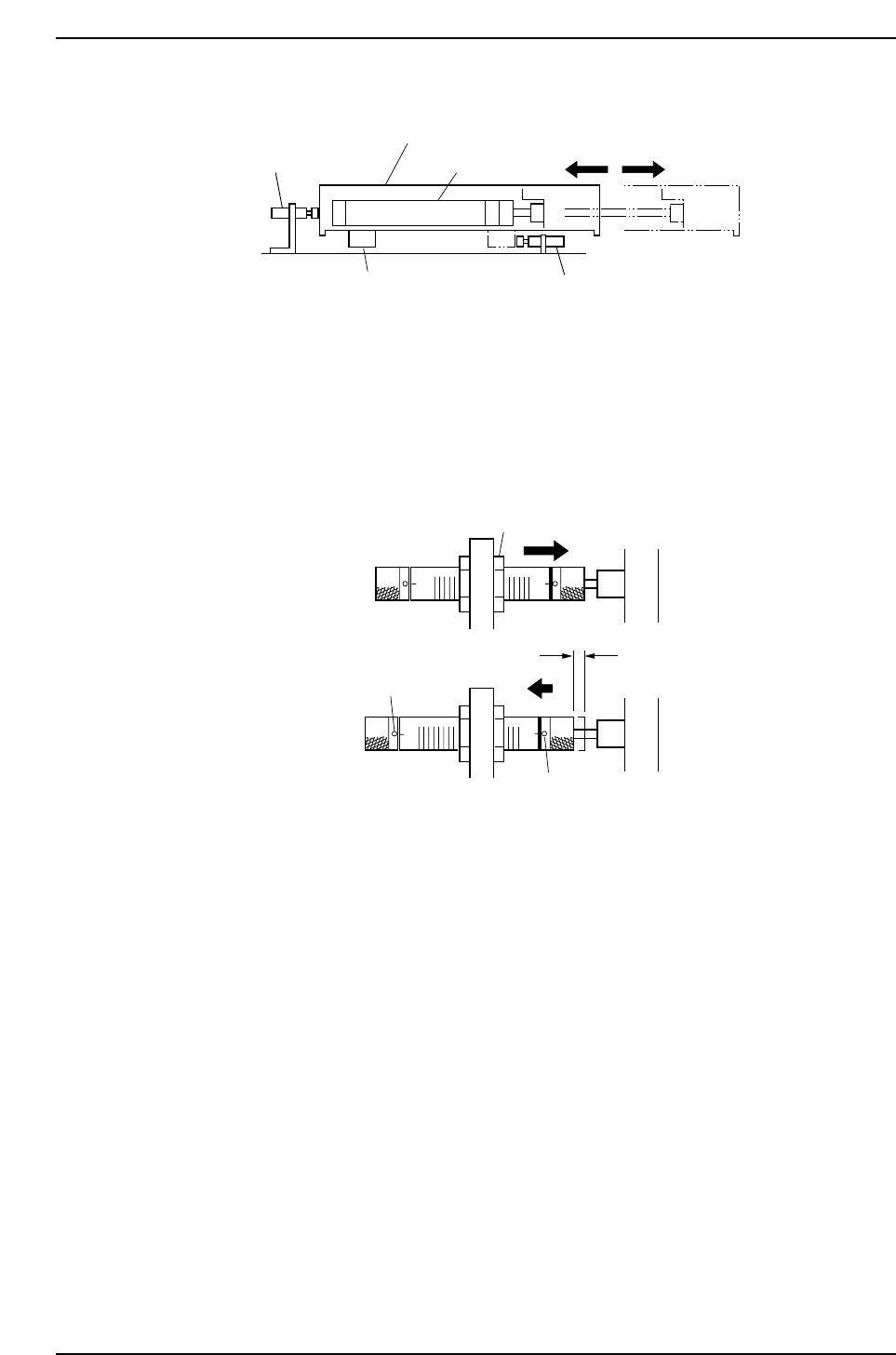
Adjust the shock absorbers for table advance and retraction.
1. Move the setup station to the fully retracted end of the pneumatic cylinder.
2. Turn the nut to adjust the position of the shock absorber.
Make the shock absorber come into contact the set-up station and press it in by an
amount corresponding to one full stroke (12.0 mm).
Return the shock absorber by 0.5 to 1.0 mm from this point, then secure it in place.
3. Set the scale indicator at "6".
4. Then move the setup station to the fully advanced end of the pneumatic cylinder,
and adjust as described above. The stopper contacts the shock absorber at the
fully advanced end.
5. Set the scale indicator at "6".
6
6
6
6
0.5-1.0 mm
Scale indicator
Scale indicator
Nut
CP6M9018
Shock absorber
Shock absorber
Pneumatic cylinder
Stopper
Setup St.
CP6M9017
Part 8 Chapter 3 Setup Station
Edition 1.0 8-3-6 CP-6-series Mechanical Reference
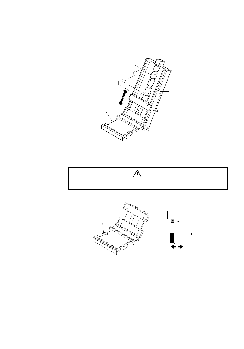
4. Elevators
Each of the elevators is a unit composed of a frame, lifter, motor, ball screw, and the like.
Elevators are used to raise or lower loaded pallets.
4.1 Adjustment of the Pallet Confirmation Sensors
Warning
Turn off the 200 V servo power before carrying out this work.
1. Set the sensor amp dial to "MIN."
2. Clamp a pallet on the "up" lifter.
At this time, adjust the position of the sensor so that the side surface of the dog
coincides with the side surface of the sensor.
Dog
Pallet confirmation sensor
Pallet
CP6M9020
Ball screw
Lifter
Motor
Frame
CP6M9019
Part 8 Chapter 4 Elevators
Edition 1.0 8-4-1 CP-6-series Mechanical Reference