CP-6-series Mechanical Reference.pdf - 第181页
3.1.3 Waste T ape Cutter • The waste tape cutter cuts tape that protrudes from feeder tips. A vacuum takes the cut tape into the waste tape box at the back side of the machine. • Rotate the adjustment rod to align the mo…
Part 5 Chapter 3 Station Adjustments
Edition 1.0 5-3-5 CP-6-series Mechanical Reference
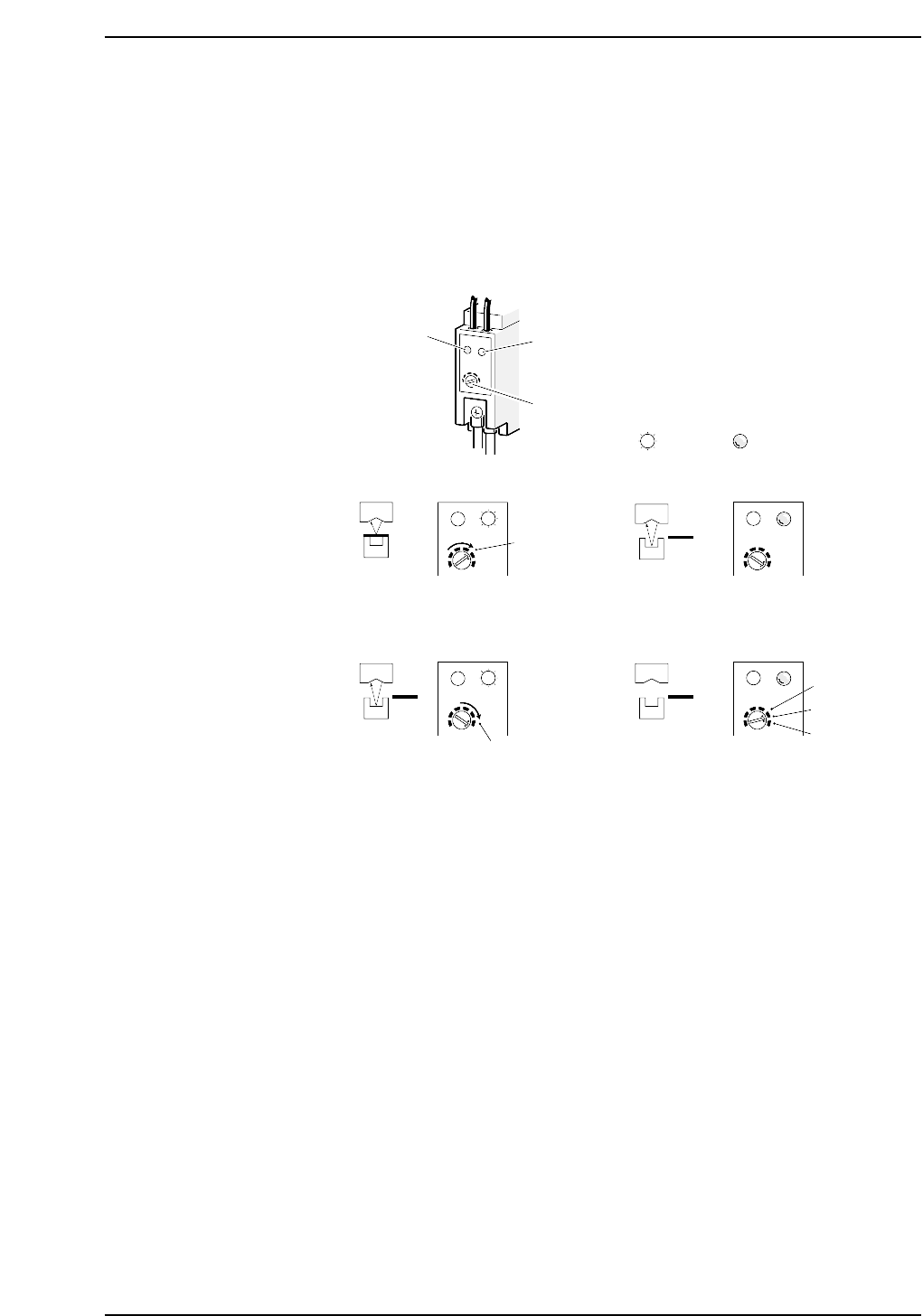
Sensor Sensitivity Adjustment
1. Rotate the sensitivity trimmer slowly to the right and ensure that the green LED
lights up at the A location.
2. Remove the paper tape from the feeder. The green LED should turn off at this
point.
3. Rotate the trimmer slowly to the right again and ensure that the green LED lights
up at the B location.
4. Set the sensitivity trimmer to be between A and B.
5. Ensure that the sensor actually detects the tape-end.
Red LED
Green LED
Trimmer
A
SET
(2)(1)
CP6M5019
B
(4)(3)
A
B
Lit Not lit
3.1.3 Waste Tape Cutter
• The waste tape cutter cuts tape that protrudes from feeder tips. A vacuum takes the
cut tape into the waste tape box at the back side of the machine.
• Rotate the adjustment rod to align the movable blade with the fixed blade.
Adjustment procedure
<4000 Type>
1. Press the EMERGENCY STOP button. This cuts the 200V servo power and leaves
on only the 100V power supply.
WARNING
• Turn off the 200 V servo power before carrying out this work.
• Exercise extreme caution when working on the machine if the cam is
not at its origin (0 deg.). Recoil of the cam axis can endanger the
operator.
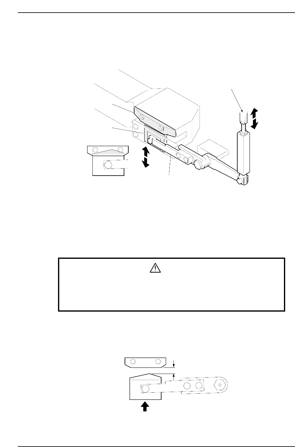
2. Use the cam handle to rotate the cam to 203°.
3. Adjust the rod so that the fixed blade completely hides the movable blade.
4. There needs to be more than 9 mm between the fixed and movable blades when
the cam is at 0°.
More than 9 mm
CP6M5021
Fixed blade
Movable blade
Cutter lever
Adjustment rod
CP6M5020
Part 5 Chapter 3 Station Adjustments
Edition 1.0 5-3-6 CP-6-series Mechanical Reference
<5000 Type>
1. Press the EMERGENCY STOP button. This cuts the 200V servo power and leaves
on only the 100V power supply.
WARNING
• Turn off the 200 V servo power before carrying out this work.
• Exercise extreme caution when working on the machine if the cam is
not at its origin (0 deg.). Recoil of the cam axis can endanger the
operator.
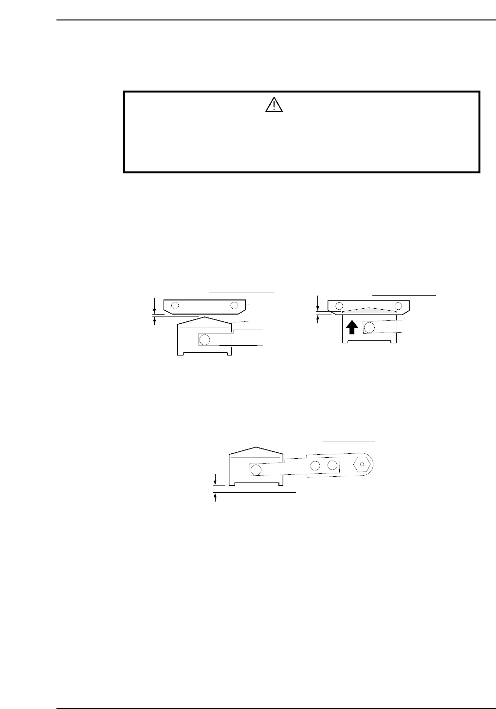
2. Rotate the cam using the handle to an angle of 153°.
3. Adjust the rod until the distance between the fixed blade and the moveable blade
is in the range of 0 ~ 0.3 mm.
4. Rotate the cam to an angle of 203°.
5. Ensure that the top edge of the moveable cutter overlaps the fixed cutter by more
than 1.0 mm.
6. Rotate the cam to 0°.
7. Ensure that there is a gap of more than 1.5 mm between the lower edge of the
moveable blade and the surface below.
More than 1.5 mm
CP6M5023
Cam angle 0°
Fixed blade
Movable blade
0 ~ 0.3 mm
More than
1.0 mm
Cam angle 153°
Cam angle 203°
CP6M5022
Part 5 Chapter 3 Station Adjustments
Edition 1.0 5-3-7 CP-6-series Mechanical Reference