CP-6-series Mechanical Reference.pdf - 第213页
3.8 Station 16 Nozzle V acuum V alve Off Station 16 uses the mechanical valve to shut off the vacuum in the nozzle. Nozzles can no longer hold parts once the vacuum is cut. Ensure that station 16 discards the parts that …
3.7 Station 13
Pre-theta Reverse Mechanism
At station 13, reverse rotation is performed so that the nozzle is returned to the rotation
angle that existed at station 3.
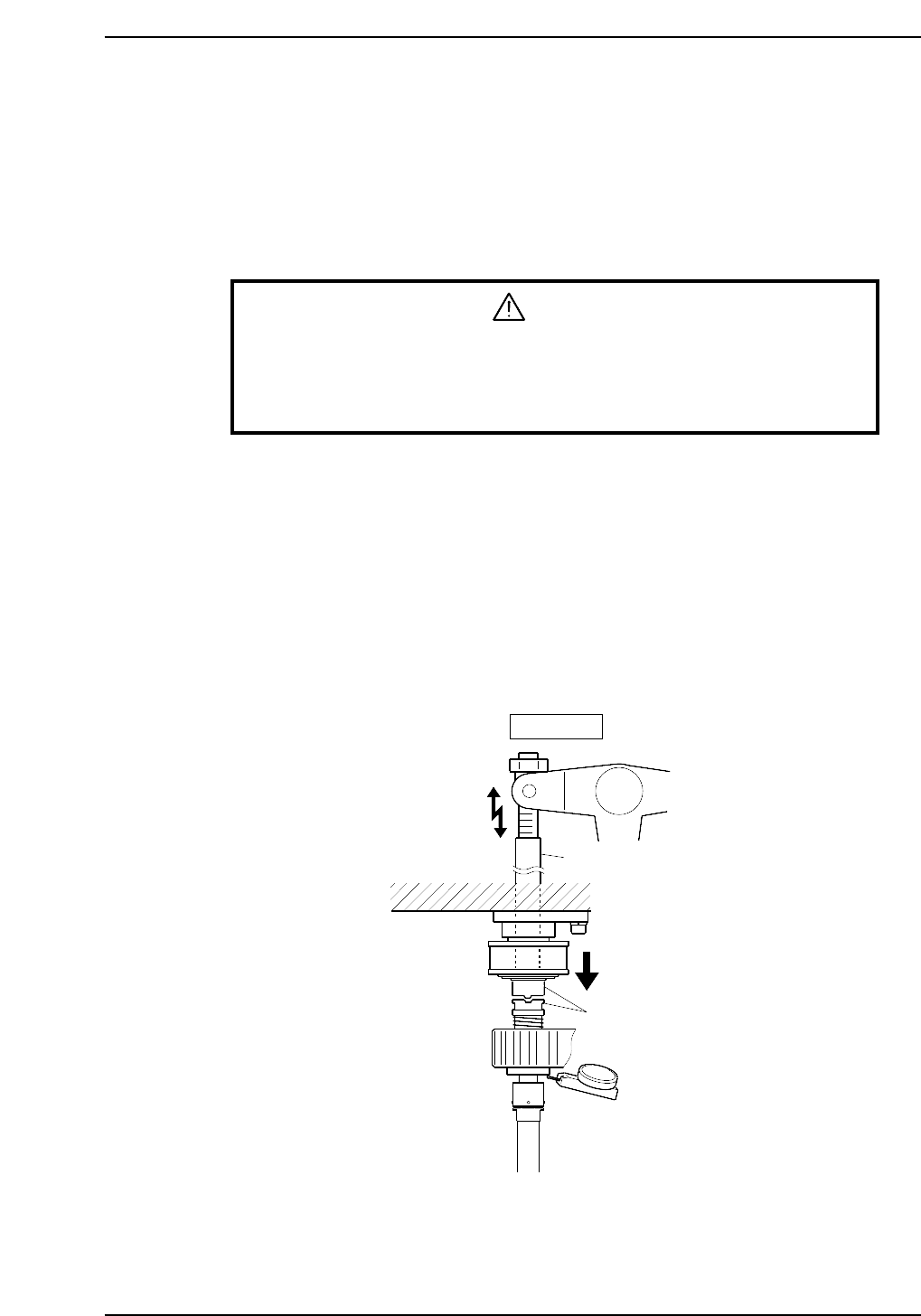
3.7.1 Clutch Engage Check
WARNING
• Turn off the 200 V servo power before carrying out this work.
• Exercise extreme caution when working on the machine if the cam is
not at its origin (0 deg.). Recoil of the cam axis can endanger the
operator.
Perform this check on the low-pressure nozzle.
1. With the cam at 0°, operate the lever by switching ON the solenoid stopper (Y02C
PRQ ROT SOL ON).
2. Set the dial gage on the under side of the nozzle shaft brake.
3. Turn the cam to 200° using the handle.
4. Confirm that the clutch is correctly engaged and that the nozzle has lowered
0.30~0.35 mm.
Note: The low-pressure nozzle refers to the nozzle axis (out of the 20) that receives the weakest
pushing pressure. Use the low-pressure nozzle for meshing checks at stations 3, 5, 10, 12
and 13.
Rod
Clutches
0.30 ~ 0.35 mm
Station 13
CP6M5058
Part 5 Chapter 3 Station Adjustments
Edition 1.0 5-3-37 CP-6-series Mechanical Reference
3.8 Station 16
Nozzle Vacuum Valve Off
Station 16 uses the mechanical valve to shut off the vacuum in the nozzle.
Nozzles can no longer hold parts once the vacuum is cut.
Ensure that station 16 discards the parts that fail vision processing.
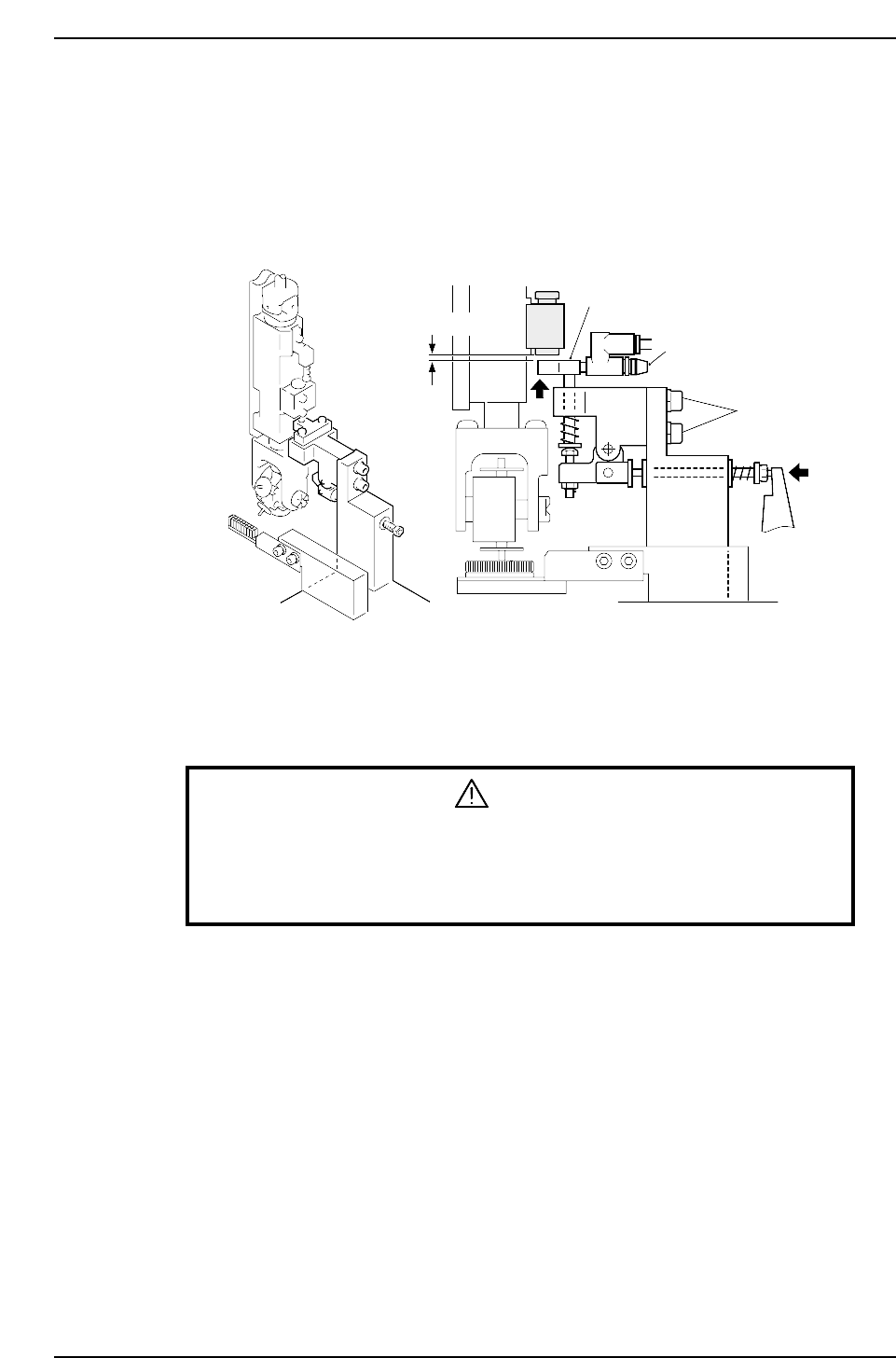
3.8.1 Nozzle Vacuum Valve Lever Height Adjustment
1. Press the EMERGENCY STOP button to take the 200V down to 100V.
WARNING
• Turn off the 200 V servo power before carrying out this work.
• Exercise extreme caution when working on the machine if the cam is
not at its origin (0 deg.). Recoil of the cam axis can endanger the
operator.
2. Move the reference head to station 16.
3. Use the cam handle to rotate the cam to 203°.
4. Ensure that there is a 0.05 ~ 0.1 mm space under the nozzle vacuum valve.
0.05 ~ 0.1 mm
Adjustment bolts
Speed regulator
Lever
CP6M5059
Part 5 Chapter 3 Station Adjustments
Edition 1.0 5-3-38 CP-6-series Mechanical Reference
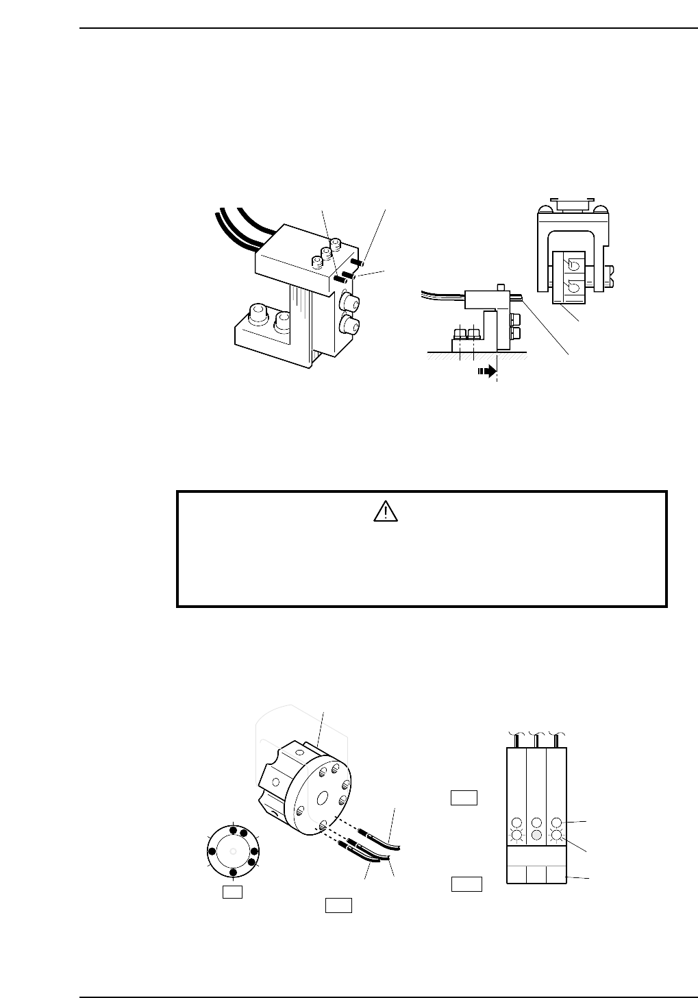
3.9 Station 17
Nozzle Detection Sensor
Station 17 uses three nozzle detection sensors to detect which of the six nozzles is
pointing straight down.
The following illustration shows the location of each sensor.
3.9.1 Checking Method
WARNING
• Turn off the 200 V servo power before carrying out this work.
• Exercise extreme caution when working on the machine if the cam is
not at its origin (0 deg.). Recoil of the cam axis can endanger the
operator.
1. Manually rotate the rotary holder to select nozzle No. 6.
The sensor reactions should be the same as shown below.
The LEDs should be red. Green LEDs are usually lit.
Rotary holder
Sensor 3
Sensor 2
Sensor 1
ON
OFF
1
2
3
4
5
6
Green LED
Red LED
Sensor No.
Front of amplifier
ON
17st
123
CP6M5061
Sensor 3
Sensor 2
Sensor 1
Flag
Sensor
To the end of
the oval hole
CP6M5060
Part 5 Chapter 3 Station Adjustments
Edition 1.0 5-3-39 CP-6-series Mechanical Reference